A frequency sweep signal generator and a method for generating a frequency sweep signal
A frequency sweep signal and generator technology, applied in electrical components and other directions, can solve the problems of reduced frequency sweep accuracy and frequency resolution, low frequency sweep speed, etc., to improve the accuracy and frequency resolution, speed, reduce external the effect of interference
- Summary
- Abstract
- Description
- Claims
- Application Information
AI Technical Summary
Problems solved by technology
Method used
Image
Examples
Embodiment 1
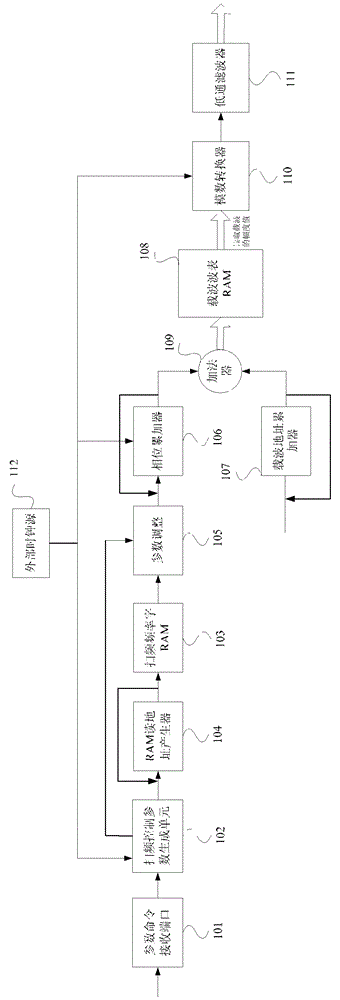
[0018] figure 2 It is a schematic structural diagram of a sweeping signal source generator according to an embodiment of the present invention, such as figure 2 As shown, the frequency sweep signal source generator of the embodiment of the present invention includes:
[0019] The parameter command receiving port 101 is used to receive frequency sweep parameters and frequency sweep commands set by users. Wherein, the frequency sweep parameters include: start frequency, stop frequency and sweep time; various parameters for controlling the sweep signal can be calculated according to the start frequency, stop frequency and sweep time.
[0020] The frequency sweep command includes: frequency sweep type and frequency sweep trigger source. Among them, the frequency sweep type includes linear frequency sweep or logarithmic frequency sweep, the user can set the frequency sweep type; the frequency sweep trigger source includes internal trigger, external trigger or manual trigger, on...
Embodiment 2
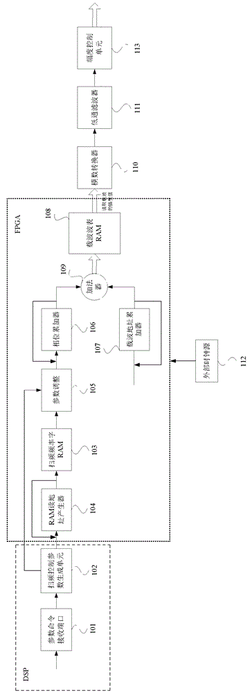
[0036] image 3 It is a schematic structural diagram of another embodiment of the frequency sweep signal generator of the embodiment of the present invention. As shown in the figure, the frequency sweep signal generator of this embodiment includes not only all the components in Embodiment 1, but also: amplitude control The unit 113 is used to adjust the signal amplitude of the final sweep signal according to the amplitude adjustment parameter. The amplitude of the signal from the low-pass filter 111 may not meet the needs of the user, so it can be controlled by the amplitude control unit. 113 to adjust the signal amplitude.
[0037] Moreover, in this embodiment, the parameter command receiving port 101 and the frequency sweep control parameter generating unit 102 are realized by DSP. Sweep frequency word RAM103, RAM read address generator 104, parameter adjustment unit 105, phase accumulator 106, carrier address accumulator 107, carrier wave table RAM108 and adder 109 are int...
Embodiment 3
[0039] Figure 4 It is a method flowchart of an embodiment of the method for generating a frequency sweep signal of the present invention. As shown in the figure, the implementation method of the frequency sweep signal of this embodiment includes:
[0040] S101. Receive frequency sweep parameters and frequency sweep commands set by the user. The frequency sweep parameters include: start frequency, stop frequency and sweep time; control can be calculated according to start frequency, stop frequency and sweep time Various parameters of the frequency sweep signal.
[0041] The frequency sweep command includes: frequency sweep type and frequency sweep trigger source. Among them, the frequency sweep type includes linear frequency sweep or logarithmic frequency sweep, the user can set the frequency sweep type; the frequency sweep trigger source includes internal trigger, external trigger or manual trigger, once the trigger source arrives, the frequency sweep signal is output once, ...
PUM
 Abstract
Description
Claims
Application Information
 - R&D
- Intellectual Property
- Life Sciences
- Materials
- Tech Scout
- Unparalleled Data Quality
- Higher Quality Content
- 60% Fewer Hallucinations
Browse by: Latest US Patents, China's latest patents, Technical Efficacy Thesaurus, Application Domain, Technology Topic, Popular Technical Reports.
© 2025 PatSnap. All rights reserved.Legal|Privacy policy|Modern Slavery Act Transparency Statement|Sitemap|About US| Contact US: help@patsnap.com


