
Throttle manifold for controlled pressure drilling

A choke manifold and drilling technology, which is applied in the direction of earthwork drilling, wellbore flushing, wellbore/well components, etc., can solve the problem of not having fluid metering, valve position detection and automatic grouting, and not being able to complete the connection of single roots. Pressure control process switching and other issues

Inactive Publication Date: 2012-05-16
CHINA PETROCHEMICAL CORP +1
View PDF6 Cites 7 Cited by
  • Summary
  • Abstract
  • Description
  • Claims
  • Application Information

AI Technical Summary

Problems solved by technology

However, the choke manifold used in conventional drilling can only realize the back pressure control when the fluid returns from the wellhead, and cannot complete the back pressure control during the single connection, the tripping process, and the process switching of each process, nor can it It has multiple functions such as fluid metering, valve position detection and automatic grouting
At present, there is no comprehensive report on choke manifolds used in controlled pressure drilling

Method used


Image

  • Throttle manifold for controlled pressure drilling
  • Throttle manifold for controlled pressure drilling

Examples


Embodiment Construction

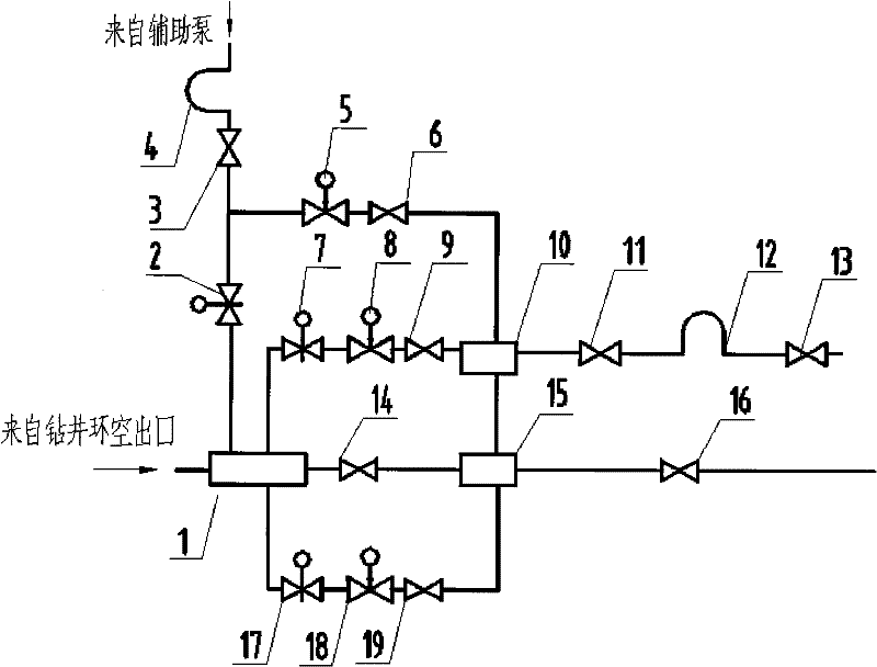
[0018] Attached below figure 1 The present invention is further described:

[0019] A choke manifold for controlled pressure drilling includes a blow-off channel, a main choke channel and an auxiliary choke channel. The discharge channel is composed of the five-way block 1, the manual flat valve 14, the four-way block 15 and the manual flat valve 16 in sequence; the main throttle channel is composed of the five-way block 1, the hydraulic flat valve 7, and the throttle valve 8 , manual plate valve 9, four-way block 10, manual plate valve 11, flowmeter 12 and manual plate valve 13 are connected by pipelines in sequence; the auxiliary throttling channel is divided into two channels by flowmeter 4 after passing through manual plate valve 3, and one channel passes through the manual plate valve 3. The hydraulic plate valve 2 is connected with the five-way block, and the other way is connected with the four-way block 10 through the throttle valve 5 and the manual plate valve 6; the...


PUM


Abstract

The invention discloses a throttle manifold for controlled pressure drilling. The throttle manifold comprises an open flow channel, a main throttle channel and an auxiliary throttle channel, wherein a flow meter of the auxiliary throttle channel is communicated with an auxiliary pump; a four-way block of the open flow channel is communicated with a four-way block of the main throttle channel through a pipeline; a five-way block of the open flow channel is connected to a casing annulus; and the flow meter is a mass flow meter and is vertically arranged, namely fluid flows through the mass flow meter from bottom to top. Wellhead back pressure required in the whole drilling process can be controlled, drilling processes can be switched, and the throttle manifold has a fluid flow measuring function.

Description

technical field [0001] The invention relates to a choke manifold for drilling, in particular to a choke manifold for controlled pressure drilling. Background technique [0002] At present, controlled pressure drilling technology has been paid more and more attention at home and abroad. In 2005, IADC and SPE held a special conference on underbalanced operation (UBO) and controlled pressure drilling (MPD) to discuss, and defined the following: controlled pressure drilling technology It is a drilling method that can control the annular pressure profile of the wellbore more accurately, and its purpose is to determine the downhole pressure window and control the annular pressure based on this. Controlled pressure drilling can accurately control downhole pressure through certain equipment and methods, and can quickly make correct adjustments according to downhole pressure changes, thereby reducing the risk and cost of drilling in formations such as narrow downhole pressure windows...

Claims


Application Information

Patent Timeline
Patent Type & Authority Applications(China)
IPC IPC(8): E21B21/08E21B21/10
Inventor 李宗清朱焕刚王岩鹏康波曹强
Owner CHINA PETROCHEMICAL CORP
Learn More