
Optic fiber connection for a force sensing instrument

An optical fiber connection and force sensor technology, which is used in the parts of surgical instruments, the use of optical devices, instruments, etc.

Active Publication Date: 2012-05-09
INTUITIVE SURGICAL OPERATIONS INC
View PDF30 Cites 9 Cited by
  • Summary
  • Abstract
  • Description
  • Claims
  • Application Information

AI Technical Summary

Problems solved by technology

One challenge is to provide surgeons with the ability to precisely "feel" tissue manipulated by surgical instruments via robotic manipulators

Method used


Image

  • Optic fiber connection for a force sensing instrument
  • Optic fiber connection for a force sensing instrument
  • Optic fiber connection for a force sensing instrument

Examples


Embodiment Construction

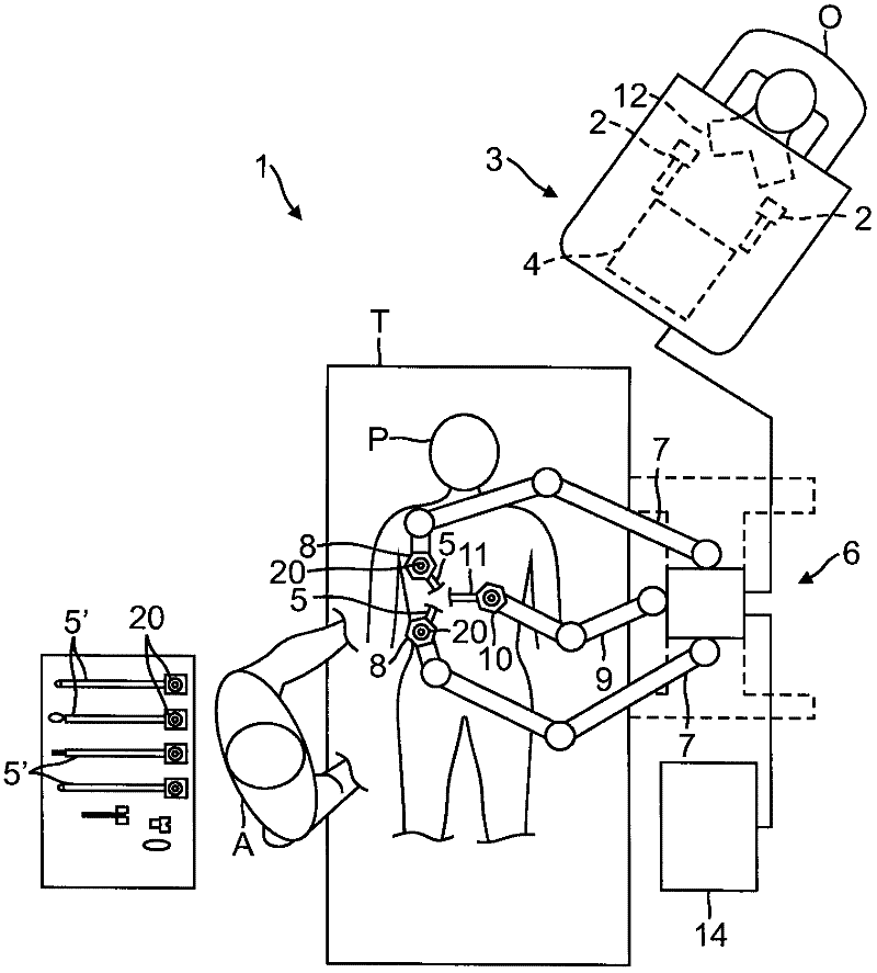
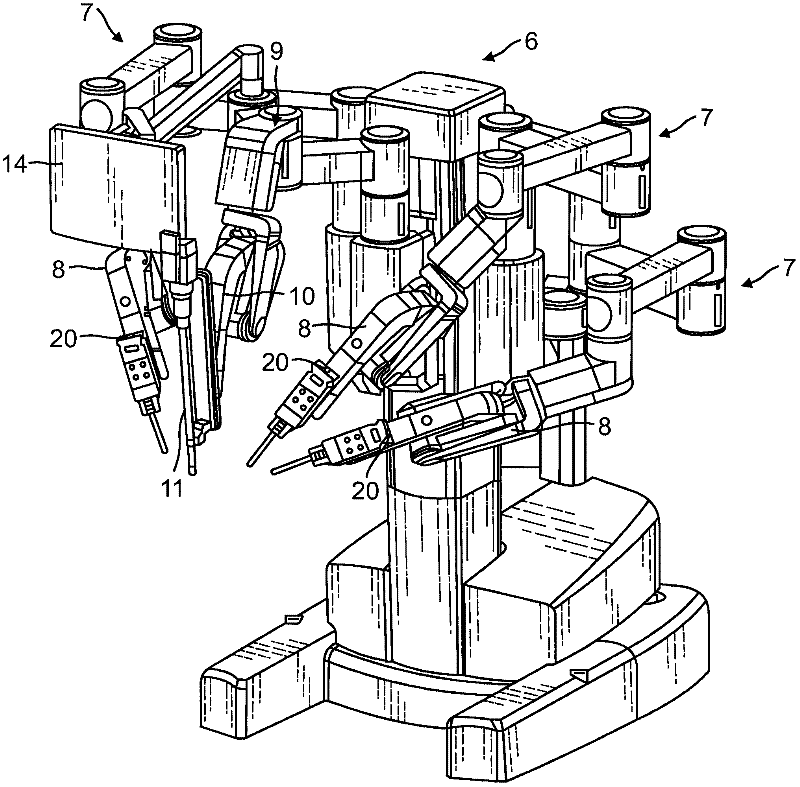
[0031] The present invention provides multi-component systems, devices and methods for sensing force during robotically assisted surgical procedures on a patient, including in particular open surgical procedures, neurosurgical procedures, and minimally invasive endoscopic procedures, such as laparoscopy , arthroscopy, thoracoscopy, and similar tests. The system and method of the present invention are highly beneficial as a telerobotic surgical system that allows a surgeon to manipulate surgical instruments from a location remote from the patient via servo mechanisms. To this end, the combined manipulator device or follower device of the present invention and attached surgical instrument are generally composed of equal degrees of freedom (e.g., 3 degrees of freedom for positioning, 3 degrees of freedom for orientation and grasping) degrees of freedom) driven by active parts, thus forming a remote monitoring system with force response or display. A description of a suitable fol...


PUM


Abstract

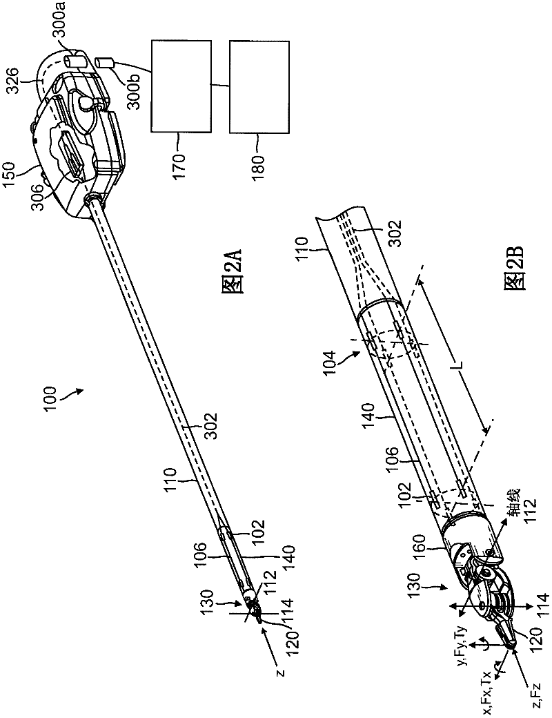
In one embodiment, a surgical instrument includes a housing linkable with a manipulator arm of a robotic surgical system, a shaft operably coupled to the housing, a force transducer on a distal end of the shaft, and a plurality of fiber optic strain gauges on the force transducer. In one example, the plurality of strain gauges are operably coupled to a fiber optic splitter or an arrayed waveguide grating (AWG) multiplexer. A fiber optic connector is operably coupled to the fiber optic splitter or the AWG multiplexer. A wrist joint is operably coupled to a distal end of the force transducer, and an end effector is operably coupled to the wrist joint.; In another embodiment, a robotic surgical manipulator includes a base link operably coupled to a distal end of a manipulator positioning system, and a distal link movably coupled to the base link, wherein the distal link includes an instrument interface and a fiber optic connector optically linkable to a surgical instrument. A method of passing data between an instrument and a manipulator via optical connectors is also provided.

Description

[0001] Cross References to Related Applications and Patents [0002] This application is related to U.S. Application No. 11 / 537,241, filed September 29, 2006, which claims priority to U.S. Provisional Application No. 60 / 755,108, filed December 30, 2005, the entire disclosure of which is for all purposes Incorporated herein by reference. [0003] This application is also related to U.S. Provisional Application No. 60 / 755,157, filed December 30, 2005, U.S. Application No. 11 / 958,772, filed December 18, 2007, U.S. Application No. 11 / 958,772, filed September 29, 2007 No. 11 / 864,974, U.S. Application No. 11 / 553,303 filed October 26, 2006, U.S. Patent Application No. 11 / 093,372 filed March 30, 2005, and U.S. Patent Nos. 6,936,042, 6,902,560, 6,879,880 , 6,866,671, 6,817,974, 6,783,524, 6,676,684, 6,371,952, 6,331,181 and 5,807,377, the entire disclosures of which are incorporated herein by reference for all purposes. technical field [0004] The present invention relates generally...

Claims


Application Information

Patent Timeline
IPC IPC(8): A61B19/00
CPCA61B2019/2234A61B19/2203A61B2019/464A61B2017/00477A61B34/30A61B2034/305A61B2090/064Y10T74/20335A61B2018/2244A61B2018/2266A61B18/00A61B2562/0266A61B34/20A61B2034/2061G01B11/16G01L1/242G02B6/12019G02B6/264G02B6/32
Inventor S·J·布鲁门克兰斯G·W·达克斯二世I·M·麦克度威尔C·J·哈瑟
Owner INTUITIVE SURGICAL OPERATIONS INC
Learn More