Backbone network with policy driven routing

A backbone network and router technology, applied in the backbone network field with policy-driven routing, can solve the problems of a large number of mappings, reducing network flexibility, and increasing router equipment costs.

Inactive Publication Date: 2012-05-09
MICROSOFT TECH LICENSING LLC
View PDF4 Cites 3 Cited by
  • Summary
  • Abstract
  • Description
  • Claims
  • Application Information

AI Technical Summary

Problems solved by technology

One such problem is that there is often a single path in the network through which packets are routed from a specific source device to a specific destination device, which reduces the flexibility of the network
Another such problem is that in order for routers in the network to pass received packets to the correct next router in the network, routers in the network typically store a list of each possible destination device address (or destination device address prefix) map
The number of mappings stored by such router devices can become very large, increasing the cost of such router devices

Method used


Image

  • Backbone network with policy driven routing
  • Backbone network with policy driven routing
  • Backbone network with policy driven routing

Examples


Embodiment Construction

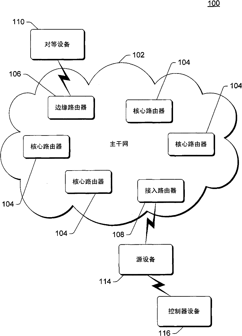
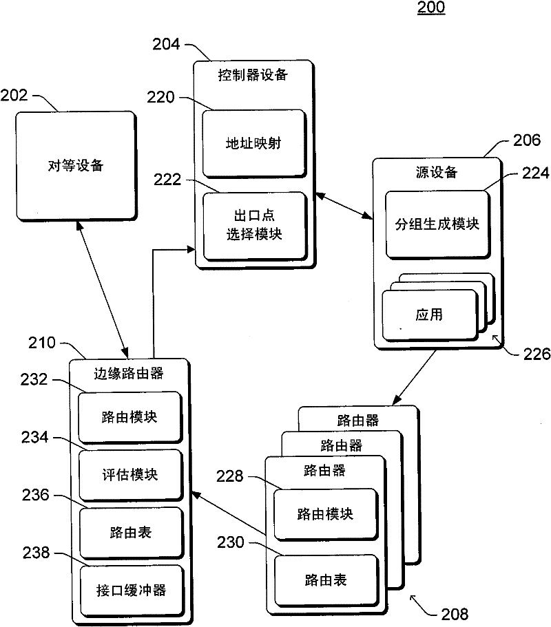
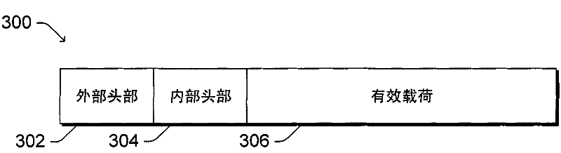
[0014] This paper describes backbone networks with policy-driven routing. A source device wishing to send a data packet over the backbone to a destination device obtains the data packet, which includes both the data to be sent (called the payload) and the destination address of the destination device. The source device accesses a controller device that maintains a mapping of destination address prefixes to exit point addresses. The exit point addresses correspond to different interfaces of one or more different edge routers of the backbone network from which data packets can potentially exit the backbone network. One of the exit point addresses is selected for the data packet based on various criteria (eg, performance of different interfaces, cost of using different interfaces, etc.). The data packet is encapsulated with the selected exit point address and routed through the backbone network based on the selected exit point address. On arrival at the edge router including th...


PUM


Abstract

The invention relates to a backbone network with policy driven routing. A source device obtains a data packet that includes both a destination address and a payload. The source device selects an exit point address of multiple exit point addresses corresponding to the destination address based on one or more policies. The source device encapsulates the data packet with a header that includes the selected exit point address, and the encapsulated data packet is provided to the backbone network. The encapsulated data packet is routed through the backbone network based on the exit point address, and an edge router of the backbone network identifies an interface of the edge router that corresponds to the exit point address. The header is removed from the encapsulated data packet, and the data packet is added to a buffer of the interface for routing to one or more other devices outside of the backbone network.

Description

technical field [0001] This paper describes backbone networks with policy-driven routing. Background technique [0002] When a source device wishes to send a data packet to a destination device over a particular network, such as a data center backbone, the source device provides the data packet to the network. Data packets are routed through the network, exiting the network at a device that onward routes the data packet to a destination device. While such networks are beneficial in transferring data packets from source devices to destination devices, they are not without problems. One such problem is that there is often a single path in the network through which packets are routed from a particular source device to a particular destination device, which reduces the flexibility of the network. Another such problem is that, in order for routers in the network to pass received packets to the correct next router in the network, routers in the network typically store a list of ...

Claims


Application Information

Patent Timeline
Patent Type & Authority Applications(China)
IPC IPC(8): H04L12/56H04L45/24
CPCH04L45/22H04L45/302H04L47/10H04L61/25
Inventor A·辛格张铭A·G·格林伯格P·拉希里D·A·马尔茨S·克里希南
Owner MICROSOFT TECH LICENSING LLC
Why Eureka
Try Eureka