clock

A movement and barrel technology, applied in the field of barrels, can solve the problem of adding barrels, etc., to achieve the effect of increasing power storage

Active Publication Date: 2017-04-12
ROLEX SA
View PDF9 Cites 0 Cited by
  • Summary
  • Abstract
  • Description
  • Claims
  • Application Information

AI Technical Summary

Problems solved by technology

Because of the way they are used, these timepieces naturally have limited dimensions, making it impossible to increase the size of the barrel, whose volume is limited by the maximum space that can accommodate it within the confines of the movement

Method used


Image

  • clock
  • clock
  • clock

Examples


Embodiment Construction

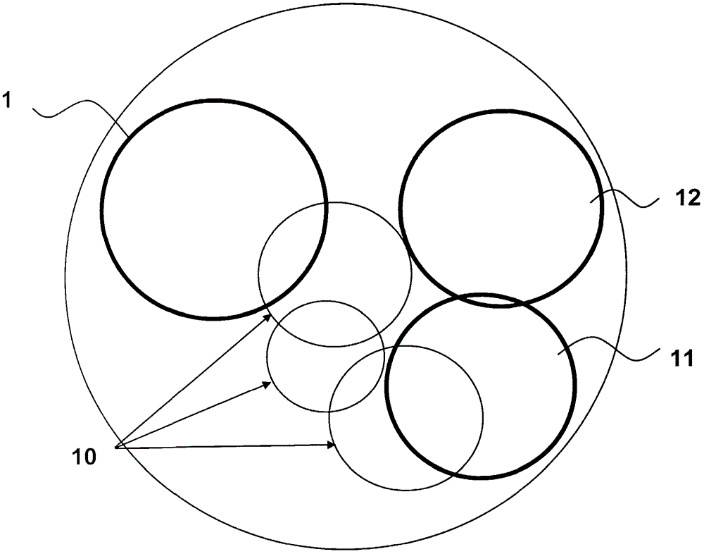
[0015] refer to figure 1 , which describes a timepiece, especially its movement. The latter comprises barrel 1 , running gear train 10 , escapement 11 and regulating mechanism 12 .

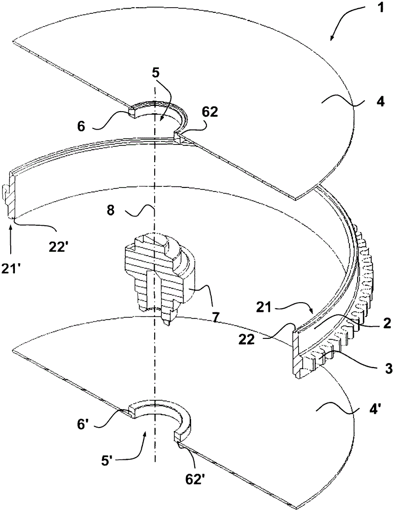
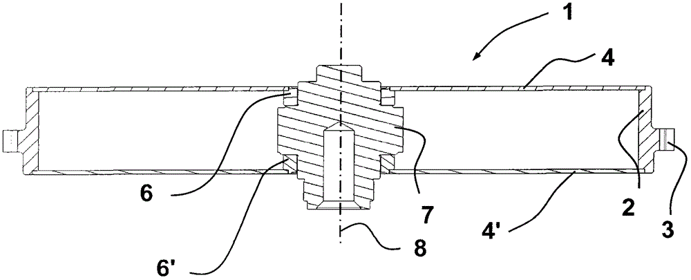
[0016] Such as Figure 2a with 2b As shown, barrel 1 consists of a thin cylindrical box, the inner space of which is designed to receive a mainspring (not shown). Around it, this barrel includes a gear 3 for driving a running gear train 10 . The barrel is composed of three distinct parts, namely a cylindrical side wall 2 surrounded by a gear wheel 3 and two disks 4, 4', one of which acts as a cover and the other as a bottom. These two disks are designed to close the space defined by the cylindrical side wall 2, each disk resting on one of the two edges 21, 21' of this wall. Preferably, the disk rests on rounded shoulder surfaces 22, 22' formed by the edges of the walls. Therefore, as Figure 2b As explained more clearly in , the inner surface of each disc may preferably be flush with t...


PUM


Abstract

The movement has a barrel (1) for a housing of a mainspring whose diameter is less than radius of movement. The barrel has a cylindrical sidewall (2) surrounded by teeth (3). The sidewall has edges closed by disks (4, 4'), where each disk has an axial opening for passage of arbor (7). Height of the housing ranges between 85 percentage and 97 percentage of total height at periphery of the barrel. One of the disks has thickness ranging between 0.04 and 0.12 mm. The opening is encircled by annular projection (6) connected to a surface of the disk that is formed from silicon, quartz and diamond.

Description

technical field [0001] The invention relates to a timepiece movement with a diameter of less than 40 mm, comprising a barrel as housing for the mainspring and having a diameter smaller than the radius of said movement. The barrel comprises a cylindrical side wall surrounded by gears. Each edge of the cylindrical side wall is sealed by a disc penetrated axially by an opening for the pivoting of the barrel arbor. The invention also relates to a timepiece comprising such a movement. Background technique [0002] In a mechanical watch, all the power required for the operation of the movement's gear train is provided by the gradual unwinding of the barrel spring. This spring is in the form of a helically wound strip. After winding, it is wound between its two ends, one held by the side wall of the barrel and the other held by the barrel arbor. The energy of the spring is transmitted through the gears of the barrel to the going gear train. [0003] Documents FR1220417 and EP1...

Claims


Application Information

Patent Timeline
Patent Type & Authority Patents(China)
IPC IPC(8): G04B1/16
CPCG04B1/16G04B33/06
Inventor 埃利奥·马里奥托
Owner ROLEX SA
Why Eureka
Try Eureka