
Method and system for conveying solvent and equipment using the system

A solvent and equipment technology, applied in the field of beverage preparation

Inactive Publication Date: 2012-05-09
KONINKLIJKE PHILIPS ELECTRONICS NV
View PDF5 Cites 5 Cited by
  • Summary
  • Abstract
  • Description
  • Claims
  • Application Information

AI Technical Summary

Problems solved by technology

[0003] This known solution for delivering solvent has the following limitation: the pumping mechanism works only with local boiling water, therefore, the solvent dispersed on the raw material (coffee grounds, tea leaves, etc.) is close to 100°C

Method used


Image

  • Method and system for conveying solvent and equipment using the system
  • Method and system for conveying solvent and equipment using the system
  • Method and system for conveying solvent and equipment using the system

Examples


Embodiment Construction

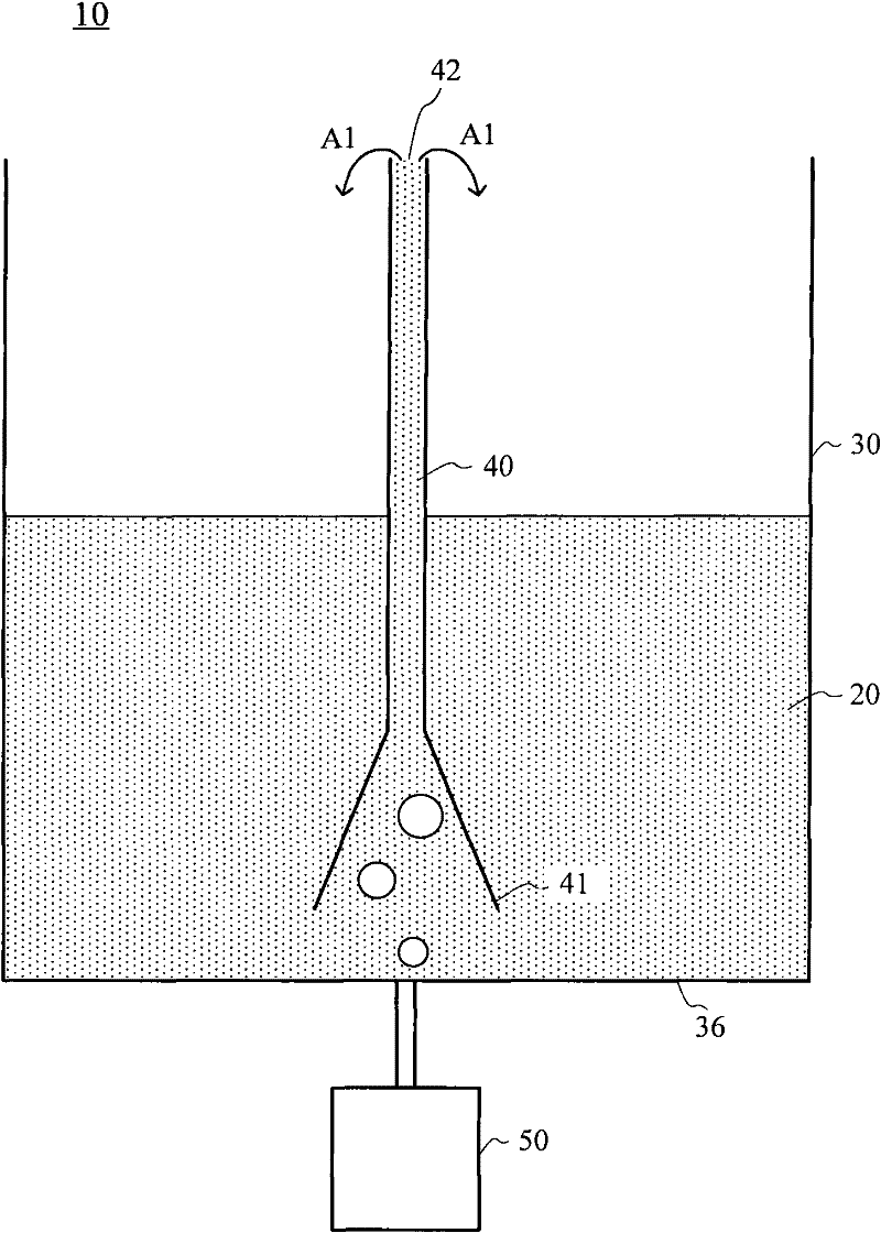
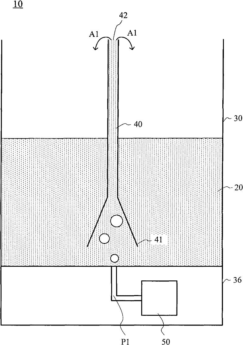
[0039] figure 1 A system for delivering a solvent according to one embodiment of the invention is shown. In this embodiment, system 10 for delivering solvent 20 includes container 30 , tubing 40 and air pump 50 .

[0040] The container 30 is used to contain the solvent 20 .

[0041] The tube 40 is located in the container 30 and has a first end 41 located near the bottom portion 36 of the container 30 and a second end 42 reaching the upper portion of the container 30 .

[0042] The air pump 50 is used to generate the gas flow discharged from the bottom part of the container 30, so that at least part of the gas flow can enter the tube 40 at the first end 41 to transport the solvent 20 in the tube 40 from the first end 41 to the second end 42, This is shown by arrow A1 at the second end 42 . Air flow is shown by the white circles in the solution 20 below the first end 41 . Air pump 50 may be of any type, preferably as image 3 Described diaphragm air pump.

[0043]It will ...


PUM


Abstract

The invention provides an improved system and method for conveying a solvent. For this reason, the system 10 for conveying the solvent 20, provided by the invention, comprises a container 30, a pipe 40 and an air pump 50, wherein the container 30 is used for accommodating the solvent; the pipe 40 is positioned in the container and provided with a first tail end 41 and a second tail end 42; the first tail end 41 is positioned at one part 36 of the container close to the bottom; the second tail end 42 reaches the upper part of the container; and the airflow 50 is used for generating airflow exhausted from the bottom part so that at least partial airflow can enter the pipe at the first tail end so as to convey the solvent in the pipe from the first tail end to the second tail end. By using the airflow generated by the air pump but not steam bubbles naturally generated by the locally boiled solvent, the solvent can reach the upper part of the pipe and obtain a temperature which is much less than the boiling temperature of the solvent.

Description

technical field [0001] The present invention relates to methods and systems for delivering solvents, and devices using the same. The invention can be used in the field of beverage preparation. Background technique [0002] There are known solutions for transporting solvent, especially from a lower point to a higher point, for example with non-pressure driven filters commonly used in coffee machines. This type of filter consists of a canister with a small chamber at its bottom placed next to a heat source. A vertical tube leads from the chamber to the top of the filter. Just below the upper end of the tube is a perforated chamber. A desired amount of solvent, such as water, is poured into the tank and a desired amount of raw material, such as coffee grounds, is placed in the top chamber. When the filter is placed on the heat source, the temperature rises until the water in the small chamber at the bottom boils. The rising water vapor bubbles caused by the boiling water, ...

Claims


Application Information

Patent Timeline
Patent Type & Authority Applications(China)
IPC IPC(8): A47J31/44
CPCA47J31/00A47J31/56A47J31/04A47J31/44
Inventor 夏允基
Owner KONINKLIJKE PHILIPS ELECTRONICS NV
Learn More