
Friction power device used for tube rotation

A technology for power devices and lamps, which is applied in the manufacture of discharge tubes/lamps, electrical components, and cold cathodes, etc., can solve the problems of large power consumption, prone to failure, and high cost, and achieves low energy saving, less failure, and higher cost. low cost effect

Inactive Publication Date: 2015-01-14
LUOYANG XINSILU ELECTRIC
View PDF2 Cites 0 Cited by
  • Summary
  • Abstract
  • Description
  • Claims
  • Application Information

AI Technical Summary

Problems solved by technology

At present, the rotating power mechanism of this kind of energy-saving lamp manufacturing equipment is generally driven by a motor. The disadvantages are high cost, large power consumption, and prone to failure.

Method used


Image

  • Friction power device used for tube rotation
  • Friction power device used for tube rotation

Examples


Embodiment Construction

[0010] The present invention is described with reference to the drawings and specific embodiments, but does not constitute any limitation to the present invention.

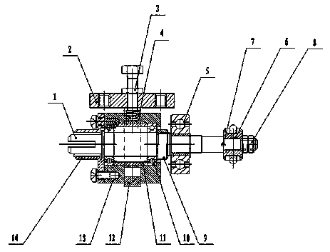
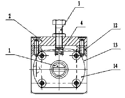
[0011] like figure 1 , figure 2 As shown, a friction power device for lamp tube rotation, the friction power device mainly includes a friction plate fixed on the base of the energy-saving lamp production equipment and a friction wheel 6 that rubs against the friction plate to generate relative rotation; the described The friction wheel 6 is arranged on one end of the main shaft 1, and is tightened by two nuts 8, and is used to fix the pin shaft 7 of the friction wheel on the main shaft, and the described pin shaft 7 is perpendicular to the main shaft; the other end of the main shaft 1 is connected to the flexible shaft Connected to form a power output shaft, which is connected with the lamp rotation mechanism; the main shaft 1 is connected in the movable shaft seat 13 through the bearing I10; the movable shaft s...


PUM


Abstract

The invention belongs to energy saving lamp production equipment. A friction power device used for tube rotation provided in the invention mainly comprises: a friction lining and a friction wheel (6). The friction wheel (6) is arranged on one end of a main shaft (1). The other end of the main shaft (1) is connected with a flexible shaft so as to form a power output shaft and is connected with a tube rotation mechanism. The main shaft (1) is connected in a movable shaft seat (13) through a bearing I (10). The movable shaft seat (13) is stuck into a U-shaped fixed plate (12) so as to form a structure that the main shaft and the movable shaft seat move up and down along the U-shaped fixed plate. The U-shaped fixed plate (12) is fixed on a fixed plate (11) of energy saving lamp production equipment. A bearing II (5), which is used to position the main shaft, is arranged on the main shaft (1). An arc boss, which corresponds with a movement track of the bearing II (5), is arranged on the friction lining. By using the device of the invention, the tube rotation of the energy saving lamp is stable and a fault is not easy to generate. And costs are low.

Description

technical field [0001] The invention belongs to energy-saving lamp production equipment, and mainly relates to a friction power device for lamp tube rotation. Background technique [0002] Today, energy saving has become an upsurge, and the energy-saving lamp industry has developed rapidly. The early energy-saving lamps have many deficiencies in luminous efficiency, service life and energy saving. In order to improve the deficiencies, a new type of energy-saving lamp The production equipment came into being. This equipment can make the energy-saving lamp tube in the rotating state during the whole drying process, which ensures the uniform powder layer on the wall of the energy-saving lamp tube and improves the quality of the energy-saving lamp. At present, the rotary power mechanism of this kind of energy-saving lamp manufacturing equipment is generally driven by a motor, which has the disadvantages of high cost, large power consumption, and prone to failure. Contents ...

Claims


Application Information

Patent Timeline
Patent Type & Authority Patents(China)
IPC IPC(8): H01J9/00
Inventor 李华文袁伟强
Owner LUOYANG XINSILU ELECTRIC
Learn More