
Double steady-state pulse electromagnetic valve control system and method and urinal and faucet

A pulse solenoid valve and control system technology, applied in valve device, valve details, water supply device and other directions, can solve the problem of different power supply time of solenoid valve on-off valve, save on-off valve time, prolong service life and save power consumption. Effect

Active Publication Date: 2013-05-08
SHANGHAI KOHLER ELECTRONICS TECH
View PDF5 Cites 0 Cited by
  • Summary
  • Abstract
  • Description
  • Claims
  • Application Information

AI Technical Summary

Problems solved by technology

[0016] In addition, due to the difference in the production process of the solenoid valve, the water pressure and water quality of the application environment, the power supply time of the solenoid valve switch valve is different.

Method used


Image

  • Double steady-state pulse electromagnetic valve control system and method and urinal and faucet
  • Double steady-state pulse electromagnetic valve control system and method and urinal and faucet
  • Double steady-state pulse electromagnetic valve control system and method and urinal and faucet

Examples


Embodiment Construction

[0037] Hereinafter, the same reference numerals refer to the same elements.

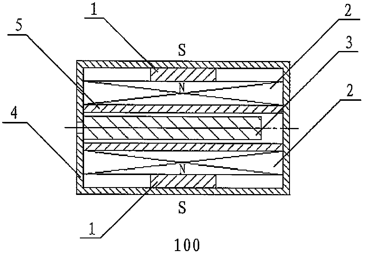
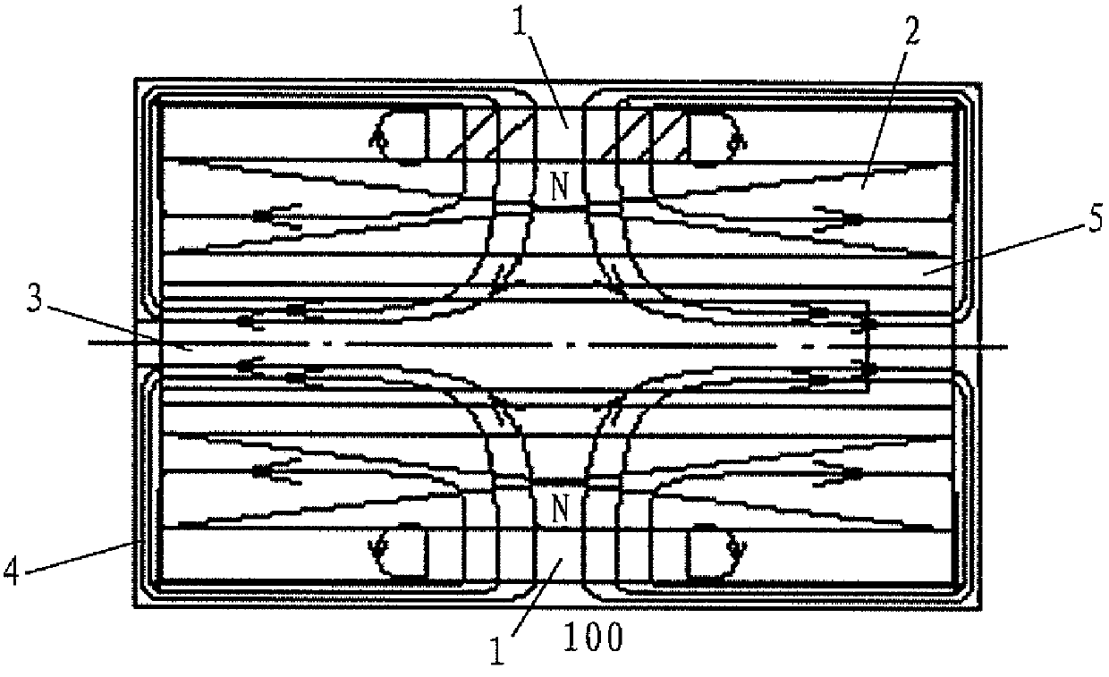
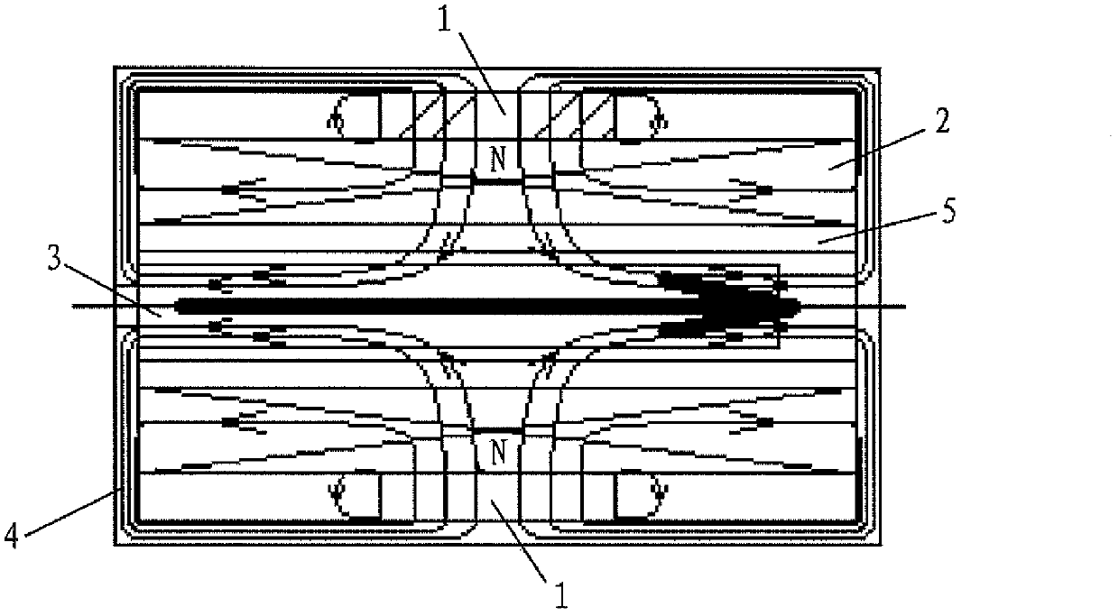
[0038] It should be noted that the basic structure of the bistable pulse solenoid valve 100 mentioned below can be described with reference to the "Background Technology" section of this specification, and the same reference numerals as above also represent the same elements.

[0039]As we all know, when the coil is energized, if a magnetic core is added inside the coil, the magnetic flux generated by the coil will be greatly increased. The axial movement of the magnetic core inside the coil will also change the magnetic flux in the coil. According to Faraday's law of electromagnetic induction, a change in magnetic flux will cause an induced electromotive force in the coil that is opposite to the direction of the original applied voltage.

[0040] Figure 5 A graph showing the current in the coil versus time during energization of a bistable pulsed solenoid valve.

[0041] Such as Figure 5 As sh...


PUM


Abstract

The present invention provides a bistable pulse solenoid valve control system and method. The control system includes a bistable pulse solenoid valve having a coil current, and including a coil frame, a coil having a magnetic flux, at least two permanent magnets, a valve core disposed inside the coil frame, and a frame configured to encapsulate the permanent magnets, the coil, the valve core, and the coil frame. The system also includes a main control circuit, a polarity conversion control circuit, and a drive current sampling detection circuit. The main control circuit is configured to generate a control signal and the polarity conversion control circuit is configured to control the direction and power on-off time of the coil current.

Description

technical field [0001] The invention relates to a control system and method for a bistable pulse electromagnetic valve, and to a urinal and a faucet adopting the control system of the bistable pulse electromagnetic valve. Background technique [0002] In existing sanitary ware, especially in faucets or urinals with automatic water discharge, an infrared sensing device is usually used to cooperate with a solenoid valve to control the water discharge. This system is powered by dry batteries, reducing dependence on the usage environment, thereby increasing the range of application. However, the electric energy of dry batteries is very limited, and at the moment when energy conservation is increasingly advocated, how to reduce the power consumption of the entire system and ensure and prolong the service life of dry batteries has become an urgent problem in this field. [0003] figure 1 The structure of a bistable pulse solenoid valve 100 in the prior art is shown. Such as fi...

Claims


Application Information

Patent Timeline
Patent Type & Authority Patents(China)
IPC IPC(8): F16K31/06E03D13/00E03D5/10
CPCE03C1/055F16K31/02F16K31/082F16K31/0675Y10T137/8376Y10T137/0324
Inventor 陈忠民高鹏程
Owner SHANGHAI KOHLER ELECTRONICS TECH
Learn More