
Rolling and sliding bearing with outer ring as sleeve

A kind of rolling bearing and outer ring technology, applied in rolling contact bearings, rotating bearings, bearings, etc., can solve the problems of poor axial accuracy, inability to install rollers or sliders, etc., and achieve long service life and installation. handy effect

Inactive Publication Date: 2012-05-02
EAST CHINA JIAOTONG UNIVERSITY
View PDF6 Cites 3 Cited by
  • Summary
  • Abstract
  • Description
  • Claims
  • Application Information

AI Technical Summary

Problems solved by technology

[0002] At present, the problem existing when rolling and sliding bearings (or cylindrical roller bearings) bear axial loads in both positive and negative directions is that if both the inner ring and the outer ring of the bearing are made into parts with fixed ribs at both ends, it cannot Install the rollers or sliders into the raceway grooves of the inner and outer rings of the bearing
The disadvantage of using these two methods is that the axial clearance of the bearing depends on the installation accuracy of the user, and the axial accuracy is poor; the movable washer may be driven to rotate by the roller or slider due to friction; Need to add other devices to fix

Method used


Image

  • Rolling and sliding bearing with outer ring as sleeve
  • Rolling and sliding bearing with outer ring as sleeve
  • Rolling and sliding bearing with outer ring as sleeve

Examples


Embodiment Construction

[0032] The present invention will be further described through an embodiment in which both ends of the rolling bearing have fixed ribs.

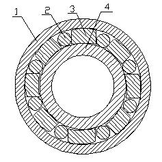
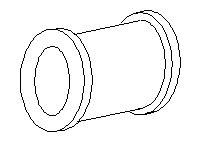
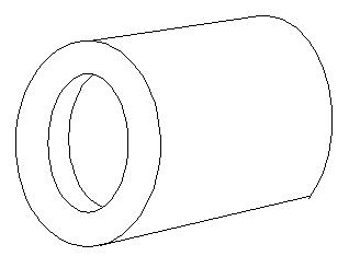
[0033] This embodiment: the inner ring is a part with fixed ribs at both ends, and the outer ring is a kit with fixed ribs at both ends to realize the purpose of fixed ribs at both ends of the inner and outer rings of the rolling bearing; the structure of the rolling bearing see figure 1 , the inner ring structure see figure 2 , see the structure of the outer ring image 3 and Figure 4 ;The outer ring is composed of an external thread ring 5 without ribs, an open spring gasket 6, an inner thread ring 7 at the left rib of the outer ring and an inner thread ring 8 at the right rib of the outer ring; an outer thread ring 5 without ribs and a left rib Internally threaded circle 7, right rib internally threaded circle 8 are connected by thread. The relationship between the split spring washer 6 and the non-wall external thread circle 5, th...


PUM


Abstract

The invention discloses a rolling and sliding bearing with an outer ring as a sleeve. The rolling and sliding bearing is characterized by consisting of the outer ring, cylindrical rollers, sliding blocks of which the number is the same as that of the cylindrical rollers, and an inner ring of which the outer rims of two ends are provided with fixed flanges, wherein the cylindrical rollers and the sliding blocks are positioned in a sliding chute formed between the outer ring and the inner ring; the number of the cylindrical rollers is equal to the number of the sliding blocks, and the cylindrical rollers and the sliding blocks are separated; the diameters of the cylindrical rollers are greater than or equal to the thicknesses of the sliding blocks in a radial direction of the bearing; the axial lengths of the cylindrical rollers are slightly less than the lengths of the sliding blocks in an axial direction of the bearing; and the cylindrical rollers and the sliding blocks are contacted with each other. The relative movement of the inner ring and the outer ring can be well restrained by the fixed flanges of the inner ring and the outer ring, so that the rolling and sliding bearing with the fixed flanges on the inner and outer rings is higher in axial positioning precision than the rolling and sliding bearing without the fixed flanges; furthermore, as the rolling and sliding bearing is a fixed whole before installation and use, the rolling and sliding bearing with the fixed flanges on the inner and outer rings is more convenient to install and is longer in service life than the rolling and sliding bearing without the fixed flanges during use.

Description

technical field [0001] The invention belongs to the field of mechanical engineering bearings. Background technique [0002] At present, the problem existing when rolling and sliding bearings (or cylindrical roller bearings) bear axial loads in both positive and negative directions is that if both the inner ring and the outer ring of the bearing are made into parts with fixed ribs at both ends, it cannot Install the rollers or sliders into the raceway grooves of the inner and outer rings of the bearing. There are mainly two solutions to this problem: one is to use the outer ring as a part with fixed ribs at both ends, and the inner ring as a part with fixed ribs at one end plus a movable gasket part as the other end rib, through the shaft The second is to use the inner ring as a part with fixed ribs at both ends, and the outer ring as a part with fixed ribs at one end plus a movable washer part as the other end rib, which is formed by pressing. The disadvantage of using the...

Claims


Application Information

Patent Timeline
IPC IPC(8): F16C19/50F16C33/58
Inventor 卢黎明
Owner EAST CHINA JIAOTONG UNIVERSITY
Learn More