
Gas drainage drill hole structure formed in coal layer and method for fabricating same

A technology of gas drainage and production method, which is applied in the direction of gas drainage, earthwork drilling, safety devices, etc., and can solve the problems of on-site construction personnel's personal safety threat, gas drainage drilling leakage, and affecting the stability of coal walls, etc. To achieve the effect of reducing accidents caused by coal wall fragments, reducing gas leakage, and improving gas drainage efficiency

Active Publication Date: 2015-03-11
CHNA ENERGY INVESTMENT CORP LTD +4
View PDF5 Cites 0 Cited by
  • Summary
  • Abstract
  • Description
  • Claims
  • Application Information

AI Technical Summary

Problems solved by technology

At the same time, in the area after the concentrated stress peak, the coal seam as a whole turns into a plastic state, and the limit plastic zone around the borehole expands sharply, and a large number of cracks are connected with the gas drainage borehole and coal roadway. Under such circumstances, even if cement mortar or polyurethane is used to seal the gas drainage borehole itself tightly, it cannot prevent the air in the roadway from entering the gas drainage borehole from the cracks in the coal walls of the two sides of the roadway, resulting in gas drainage boreholes. serious air leak
Moreover, with the widespread promotion and application of directional long drilling in my country, during the construction process of directional long drilling, due to the high pressure water (generally reaching about 30-40MPa) will discharge the coal powder from the drilling hole to the roadway. The broken medium in the pressure relief zone of the coal wall has a certain scouring effect, which seriously affects the stability of the coal wall, and there is a danger of fragmentation, which also poses a serious threat to the personal safety of the construction workers on site

Method used


Image

  • Gas drainage drill hole structure formed in coal layer and method for fabricating same
  • Gas drainage drill hole structure formed in coal layer and method for fabricating same
  • Gas drainage drill hole structure formed in coal layer and method for fabricating same

Examples


Embodiment Construction

[0035] The method for forming a gas drainage borehole in a coal seam according to the present invention will be described in detail below with reference to the accompanying drawings and examples.

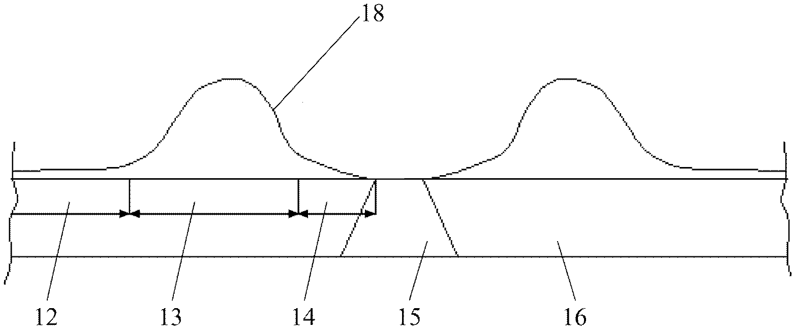
[0036] figure 1 It is a schematic diagram showing the stress curve 18 of the two sides of the coal roadway during the driving process of the coal roadway. Such as figure 1 As shown, during the tunneling process of the coal roadway, the original stress balance of the coal seam 12 is destroyed, and a three-dimensional structure including the pressure relief zone 14, the stress concentration zone 13 and the original stress zone 12 is formed in front of the coal walls of the two sides of the coal roadway. A stress zone, wherein, the width of the pressure relief zone 14 extends inwardly from the coal walls of the two sides of the coal roadway 15 approximately by 5-7m. In this area, the coal seam 16 will expand under the action of the concentrated stress in front of the working face. Th...


PUM


Abstract

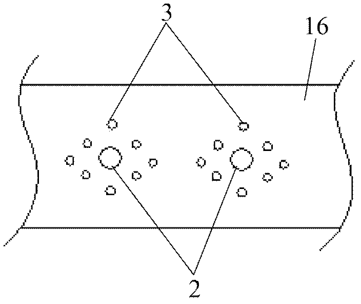
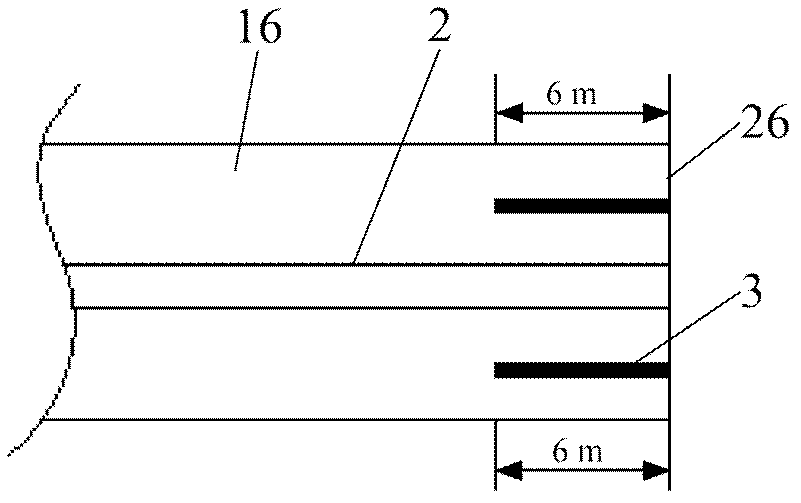
The invention provides a gas drainage drill hole structure formed in a coal layer and a method for fabricating same. The gas drainage drill hole structure comprises a gas drainage drill hole (2) and multiple auxiliary holes (3) arranged around the gas drainage drill hole; and the auxiliary holes are filled with expanding agents. According to the gas drainage drill hole structure and the method for fabricating same, coal wall cracks in two coal wall pressure relief bands on a roadway can be effectively blocked to block a channel for air in the roadway to flow to the gas drainage drill hole so as to reduce the air leakage quantity of the gas drainage drill hole and greatly improve the gas drainage efficiency. In addition, the gas drainage drill hole structure is capable of improving the stability of the coal walls and reducing the accidents of injuring the people by coal wall cavings, and has important meaning in field construction safety.

Description

technical field [0001] The invention relates to the technical field of gas drainage borehole sealing in high-gas mines or coal and gas outburst mines, and in particular relates to a gas drainage borehole structure formed in a coal seam and a manufacturing method thereof. Background technique [0002] Gas drainage is the root cause of comprehensive management of mine gas in high gas mines and coal and gas outburst mines. There are many methods of gas drainage, which can be divided into coal seam drainage, adjacent layer drainage, and goaf drainage according to space; According to the time, it can be divided into pre-mining extraction, extraction while digging, extraction while mining, and gob drainage; according to the extraction process, it can be divided into roadway drainage method, drilling drainage method, combined drainage method of roadway and drilling According to whether it is affected by pressure relief, it can be divided into non-pressure relief pumping, pressure r...

Claims


Application Information

Patent Timeline
Patent Type & Authority Patents(China)
IPC IPC(8): E21F7/00E21B33/13
Inventor 周连春彭建国姚平郝瑞明魏里阳常鸿王洪武王恒晓宋文义胡千庭董钢锋王振郑雷张世明
Owner CHNA ENERGY INVESTMENT CORP LTD
Learn More