
Method and means for a high power solar cell

A solar cell, energy technology, applied in circuits, photovoltaic power generation, electrical components, etc., can solve problems such as leakage

Inactive Publication Date: 2012-04-25
米科・韦内宁
View PDF10 Cites 2 Cited by
  • Summary
  • Abstract
  • Description
  • Claims
  • Application Information

AI Technical Summary

Problems solved by technology

US 5021100 has a serious problem that the reflective film is bi-directional, that is, any reflected photons in the first solar cell will leak through the reflective film back to the second solar cell and since these photons cannot be in the second solar cell are absorbed to generate phonons and heat

Method used


Image

  • Method and means for a high power solar cell
  • Method and means for a high power solar cell
  • Method and means for a high power solar cell

Examples


Embodiment Construction

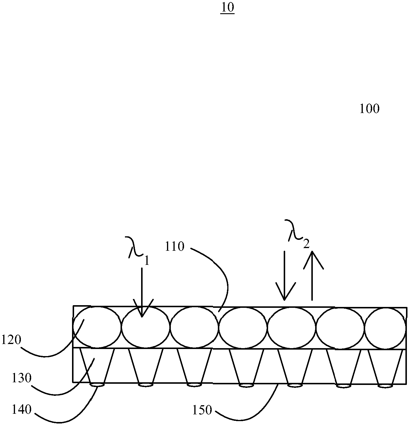
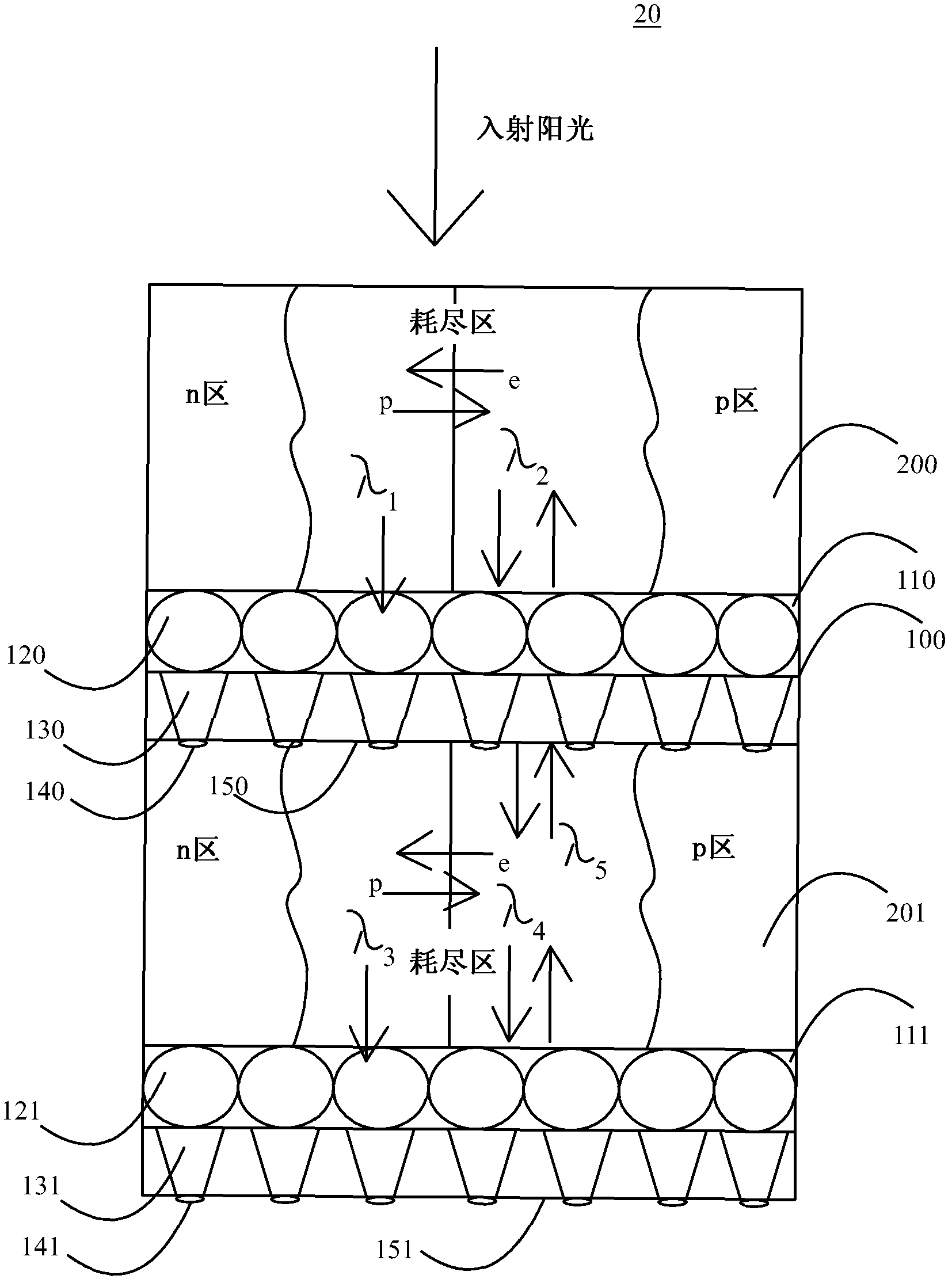
[0047] figure 1 An exemplary embodiment of a photonic filter 100 is shown isolated (ie, placed between two solar cell layers) within a tandem solar cell. In this figure, it is assumed that the sunlight incident side is upward. In some embodiments, λ 2 The photon ratio λ 1 The photon has a higher energy, that is, λ 2 1 , but according to the invention it is also possible to construct the filter 100 inversely, ie it reflects low-E photons while letting high-E photons pass. The photonic filter 100 has a reflector 110 on the sunlight incident side. Reflector 110 may be a Rugate filter or any other optical bandpass filter according to the invention. Below the reflector is at least one concentrating device for unreflected photons, ie photons passing through the reflector 110 . These concentrating devices are usually lenses of any shape (can be circular as shown in the figure), and converge the photon group into a funnel (horn) 130 with a reduced cross-section. The funnel may ...


PUM


Abstract

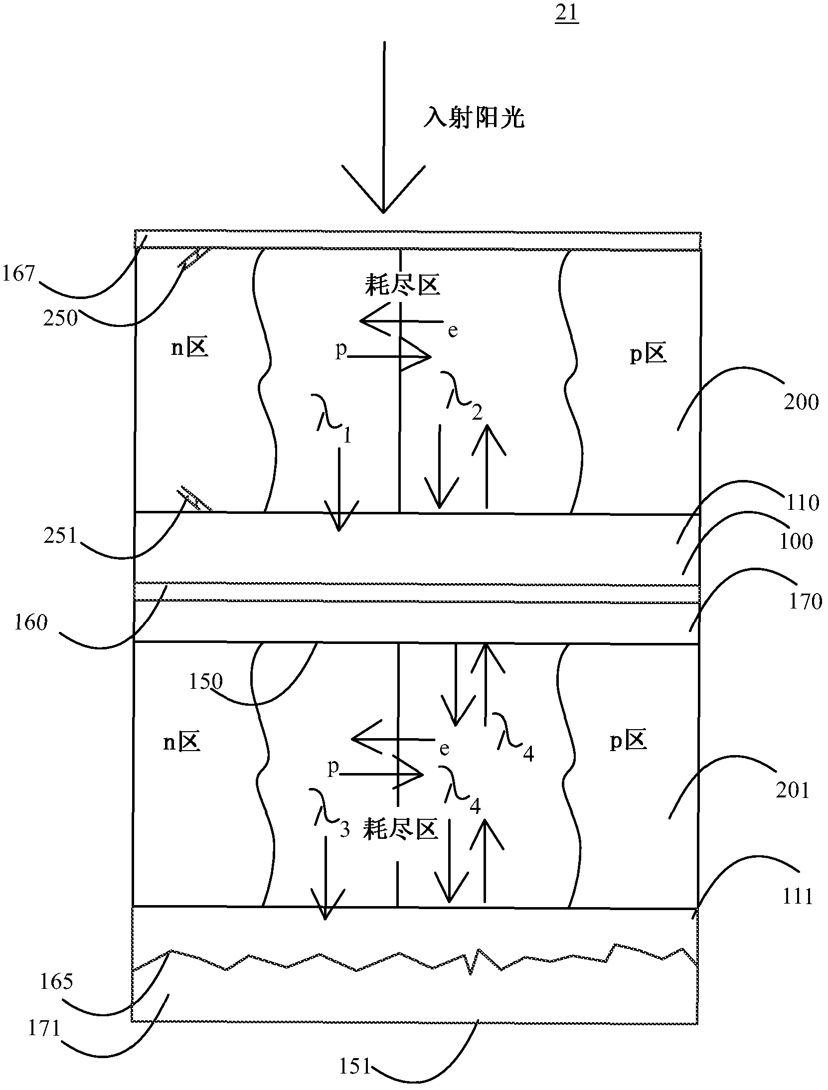
The invention relates to methods and means for improving the power generated, and thus efficiency of solar cells (20, 30). The best mode of the invention at present is considered to be a double or triple junction tandem solar cell (20, 30) that has one or two photon filters (100, 101) of the invention in between the solar cell layers (200, 201, 202, 203), respectively. The photon filter (100, 101, 102) is arranged to reflect photons with wavelength shorter than x and arranged to be transparent to photons of wavelength longer than x by focussing the said lower energy photons out of small area apertures (140, 141) on the other side of the photon filter (100, 101, 102) and arranging the other side of the photon filter (100, 101, 102) to reflect (150, 151) at least some of the said photons of wavelength longer than x.; By using the photon filters (100, 101, and 102) of the invention in between the solar cell layers (200, 201, 202, and 203), photons can be trapped between filters to solar cell layers at an energy at which the quantum efficiency (QE) of the solar cell layer is the best.

Description

technical field [0001] The present invention relates to methods and devices for increasing the power and efficiency of solar cell generation. Background technique [0002] Photovoltaic solar cells are a recently discovered new method of generating energy that began with satellite power systems in the former Soviet Union and the United States in the 1950s. Photovoltaic solar cells generate electricity with very little environmental impact and are thus in demand by the public. A problem with current photovoltaic solar cells is that they do not generate enough energy for their cost and / or surface area to make them economically viable. [0003] Therefore, many techniques have been proposed to improve the efficiency of solar cells. EP 1724841A1 describes a multilayer solar cell in which a plurality of solar cell modules are incorporated and integrally laminated so that the different sensitivity wavelength bands are such that the module whose center wavelength of the sensitivity...

Claims


Application Information

Patent Timeline
Patent Type & Authority Applications(China)
IPC IPC(8): H01L31/06H01L31/052
CPCY02E10/52H01L31/06H01L31/0522H01L31/0543H01L31/0547H01L31/0725H01L31/054H01L31/0232
Inventor 米科·韦内宁
Owner 米科・韦内宁
Learn More