
Combined cord clip

A technology for cable clips and connecting cables, applied in bridge parts, bridges, buildings, etc., can solve the problems of uneven bolt preload, poor stress on the cable clip structure, long length of a single long cable clip, etc. Less stress, good anti-corrosion effect, and high construction efficiency

Active Publication Date: 2014-01-15
LIUZHOU OVM MASCH CO LTD
View PDF6 Cites 0 Cited by
  • Summary
  • Abstract
  • Description
  • Claims
  • Application Information

AI Technical Summary

Problems solved by technology

[0004] The technical problem to be solved by the present invention is: to provide a combined cable clamp to solve the problem that the length of a single long cable clamp is too long, the construction efficiency is low, the bolt pre-tightening force is uneven or cannot reach the design value, and the force of the cable clamp structure is not good. and other problems; the second is to solve the problems of anti-corrosion and beautiful line shape of the main cable existing in the two existing cable clamp structures

Method used


Image

  • Combined cord clip
  • Combined cord clip
  • Combined cord clip

Examples


Embodiment 1

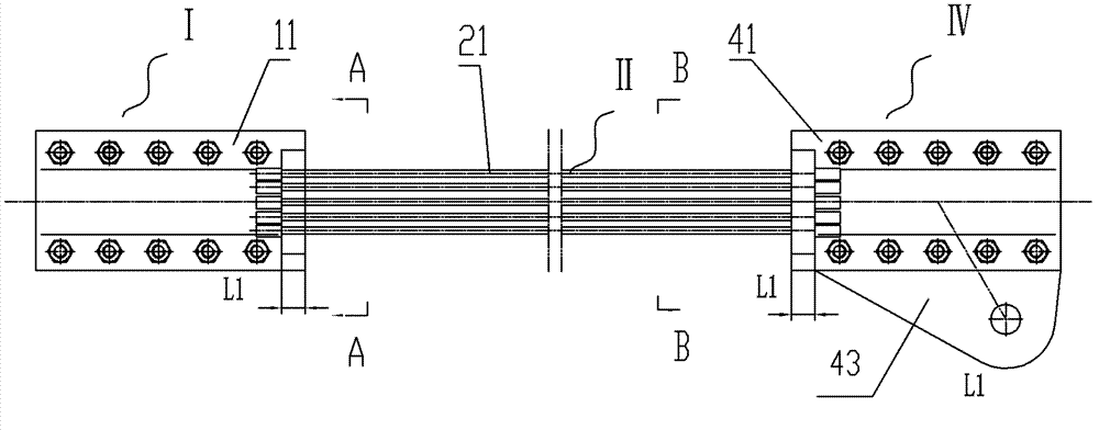
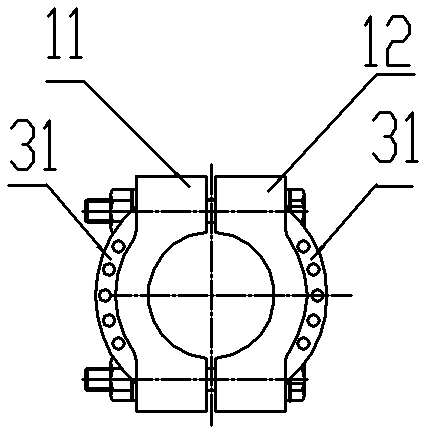
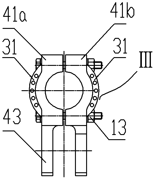
[0068] A steel strand connecting the left and right halves of a separate combined cable clamp, such as Figure 1-1 to Figure 1-4 As shown, the cable clamp IV with lugs is a left and right halves separated cable clamp 41 with lugs, and the cable clamp I without suspension points is two semicircular cable clamp bodies 11 and 12 placed on the left and right. The connecting cable body II of the connecting mechanism is a steel strand 21, and the fixing member III is an anchoring plate 31 connected with a cable clamp without a lifting point or a left and right half-separated cable clamp 41 with lugs. The connection mode between the anchor plate 31 and the cable clamp without suspension point includes making one body with each semicircular cable clamp body of the cable clamp without suspension point respectively or making it separately and then fixedly connected with it; the anchor plate 31 is separated from the left and right halves The connection mode of the ear plate cable clamp 41...

Embodiment 2

[0070] A steel strand connecting the upper and lower halves of a separate combined cable clamp, such as Figure 2-1 to Figure 2-3As shown, the non-suspension point cable clamp I is two semicircular cable clamp bodies 11 and 12 placed up and down, the connecting cable body II of the connecting mechanism is a steel strand 21, and the ear plate The cable clamp is the upper and lower two half-separated type with lug plate cable clamp 42, and the fixed part III is the anchor plate 31 connected with the no-sling point cable clamp or the upper and lower two half-separated type with ear plate cable clamp 41 respectively, The connection mode between the anchor plate 31 and the cable clamp without suspension point includes making one body with the semicircular cable clamp bodies of the cable clamp without suspension point respectively or making it separately and then fixedly connected with it; the anchor plate 31 is separated from the upper and lower The connection mode of the ear plate...

Embodiment 3

[0073] A finished cable with fork lugs at both ends or a steel tie rod connecting the left and right halves of a separate combined cable clamp; Figure 3-1 to Figure 3-3 As shown, the non-suspension point cable clamps are two semicircular cable clamp bodies 11, 12 placed left and right, the connecting cable body II of the connecting mechanism is a finished cable 22 or a steel tie rod 23, and the ear plate The cable clamp is a left and right half-separated type with lug plate cable clamp 41, and the fixed part III is arranged on the left and right sides of the no-sling point cable clamp or the left and right two-half separated type with lug plate cable clamp 41, and is connected with the non-suspended Point cable clip I or the pull plate 32 with the left and right halves of the separated cable clip 41 with lugs connected into one, the connection mode of the pull plate 32 and the cable clip without lifting point includes respectively connecting with each semicircle of the cable c...


PUM


Abstract

The invention discloses a combined cord clip, comprising a cord clip with an ear plate, a hanging-point-free cord clip, and a connecting mechanism for connecting the cord clip with the ear plate with the hanging-point-free cord clip into a whole, wherein the hanging-point-free cord clip is composed of two semicircular cord clip bodies which are connected by a high-strength bolt pair into a whole and clamped on a main cable; the cord clip with the ear plate comprises left and right separated type cord clips with ear plates or upper and lower separated type cord clips with ear plates, and the left and right separated type cord clips with ear plates or upper and lower separated type cord clips with ear plates are connected by a high-strength bolt pair into a whole and clamped on the main cable; the connecting mechanism comprises a connecting cord body and a fixing piece; the connecting cord body comprises a steel strand, a finished cord or a steel tie trod; the fixing mechanism comprises an anchoring plate, a pulling plate or a support plate; and two ends of the connecting cord body are respectively connected with the fixing piece fixed on the cord clip with the ear plate or the hanging-point-free cord clip so as to connect the cord clip with the ear plate and the hanging-point-free cord clip into a whole. The combined cord clip is optimized in structure, and reduced in the production cost of the cord clip, therefore, the stress of the cord clip structure is safer, and the stress and the anti-corrosion effects of the main cable are better.

Description

technical field [0001] The invention relates to an accessory for clamping a main cable of a suspension bridge, in particular to a cable clamp of a suspension bridge. Background technique [0002] At present, with the rapid development of self-anchored suspension bridges, the design force of the suspenders of self-anchored suspension bridges is also increasing. In addition, self-anchored suspension bridges have the characteristics of large rise-span ratio. It is required to meet greater anti-sliding force. Therefore, there are two solutions. One is to lengthen the design length of the cable clamp, but the problem brought by the long cable clamp is: the number of bolts is more, due to the mutual influence between the bolts, There are many requirements for bolt pre-tightening times, which seriously affects the construction efficiency, and the construction of bolt pre-tightening force is difficult to meet the design requirements, and the loss of bolt pre-tightening force is seri...

Claims


Application Information

Patent Timeline
Patent Type & Authority Patents(China)
IPC IPC(8): E01D19/16
Inventor 石伟李文献黄家珍李华萍邹全覃巍巍梁黎霞
Owner LIUZHOU OVM MASCH CO LTD
Learn More