
Double lumen catheter

A double-lumen catheter and catheter technology, applied in the direction of catheters, suction instruments, hollow probes, etc.

Inactive Publication Date: 2012-04-18
JOLINE GMBH & CO KG
View PDF6 Cites 1 Cited by
  • Summary
  • Abstract
  • Description
  • Claims
  • Application Information

AI Technical Summary

Problems solved by technology

[0013] Despite various solutions suggested and / or provided in the prior art for dual lumen catheters, problems with recirculation, clots and inappropriate flow rates persist

Method used


Image

  • Double lumen catheter
  • Double lumen catheter
  • Double lumen catheter

Examples


Embodiment Construction

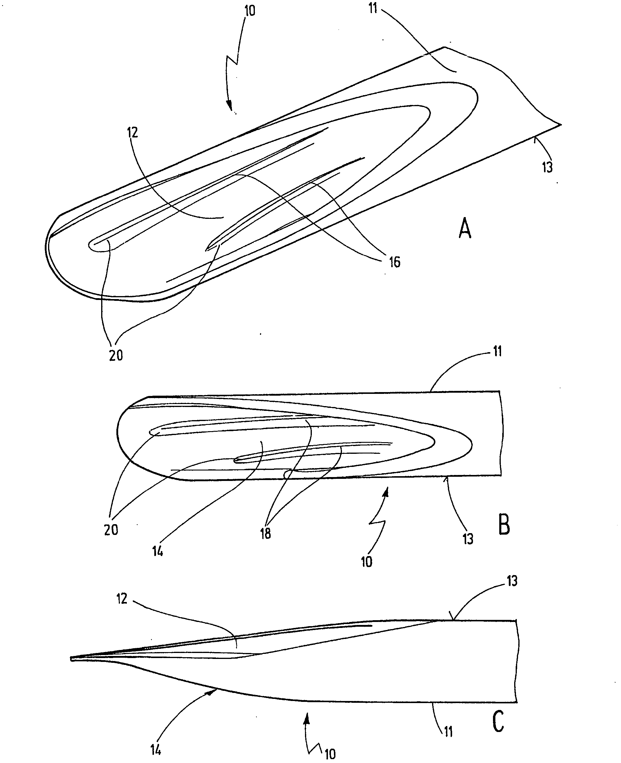
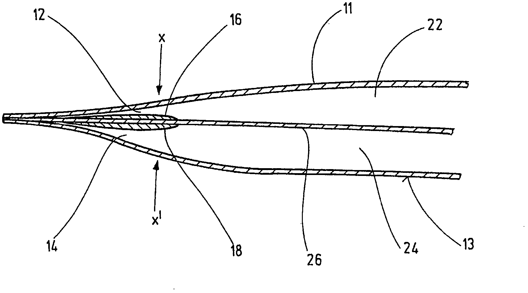
[0051] figure 1 Shown is the distal end of a dual lumen catheter according to an embodiment of the present invention, the elongate tubular body 11 of which is partially depicted. exist figure 1 , a dual lumen catheter tip 10 according to an embodiment of the present invention is shown, as in figure 1 As shown in a, the opening of the inflow cavity 22 is designated as 12, while as in figure 1 As shown in b, the opening of the return chamber 24 is designated 14 . Openings 12 and 14 are separated via a partition wall (in figure 1 not shown). figure 1 c shows a side view of the tip 10 showing the opening 12 of the inflow chamber 22 and the opening 14 of the return chamber 24 . exist figure 1 In the embodiment shown in , the tip 10 comprises ridges 16 and 18 which extend in the region of the openings 12 and 14 of the inflow chamber 22 and return chamber 24 and along the longitudinal portion of said tubular body. exist figure 1 In the embodiment shown in , the distal end 20 ...


PUM


Abstract

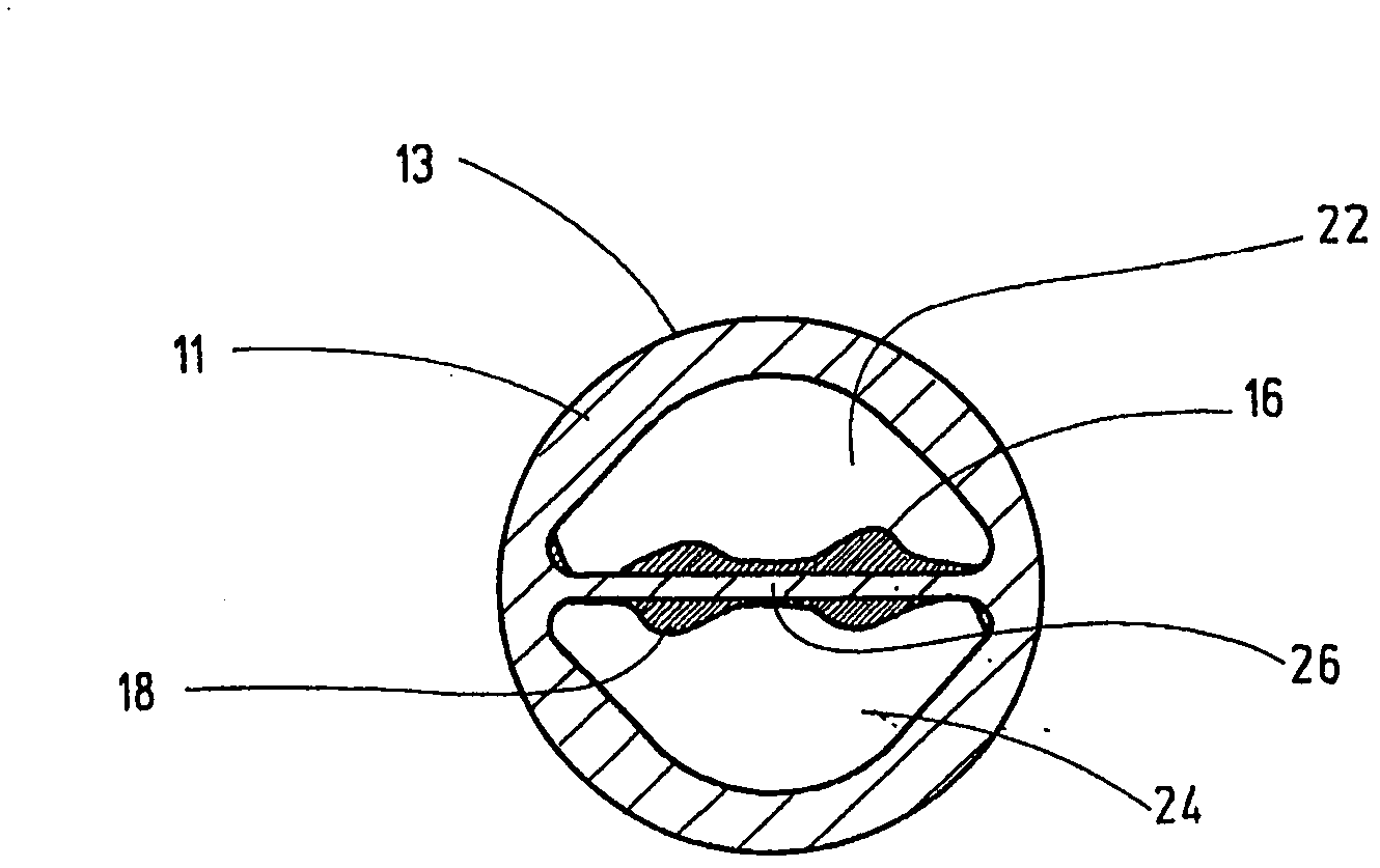
The present application concerns a double-lumen catheter, an elongated tubular body (11) having a proximal end and distal end, a divider wall (26) extending along an interior of said tubular body (11) and separating said interior into an intake lumen (22) and a return lumen (24), and the intake lumen (22) and said return lumen (24) each comprising a bevelled opening (12; 14) sloping toward the divider wall (26) and toward the distal end of the tubular body (11), respectively, the openings (12; 14) being divided by the divider wall (26), such, that one side of the divider wall (26) faces the intake lumen (22) and the other side of the divider wall (26) faces the return lumen (24). Further, the divider wall (26) at the distal end of the tubular body (11) on at least one of its two sides comprises at least one ridge (16; 18) extending in the area of the openings (12; 14) and along a longitudinal portion of the tubular body (11).

Description

technical field [0001] The present invention relates to dual lumen catheters for delivering or withdrawing fluids from a patient. The catheter includes an elongated tubular body having a proximal end and a distal end, the distal end being positioned within a vessel of the patient, a dividing wall extending along the interior of the tubular body and dividing the interior into an inflow lumen and a backflow lumen lumen, the inflow lumen and the return lumen each extend from the proximal end to the distal end of the tubular body, the inflow lumen and the return lumen are defined by the outer wall and the partition wall, and the inflow lumen and the reflux lumen each include oblique openings inclined toward the partition wall and toward the distal end of the tubular body, the openings are separated by the partition wall so that one side of the partition wall faces the inflow chamber while the other side of the partition wall faces the return chamber. Background technique [00...

Claims


Application Information

Patent Timeline
Patent Type & Authority Applications(China)
IPC IPC(8): A61M25/00
CPCA61M25/0071A61M1/3661A61M2025/0073A61M25/0032A61M25/003A61M25/0068A61M2001/3661A61M2025/0031
Inventor 安塞尔姆·施特格斯奥利维耶·舒勒
Owner JOLINE GMBH & CO KG
Learn More