
Reference voltage regulation method and circuit as well as constant-current source driving circuit utilizing same

A technology of reference voltage circuit and driving circuit, which is applied in the direction of lamp circuit layout, electric light source, electroluminescence light source, etc., and can solve the problems of reducing the efficiency of LED system and large power loss of constant current source, etc.

Active Publication Date: 2012-04-11
SILERGY SEMICON TECH (HANGZHOU) CO LTD
View PDF2 Cites 13 Cited by
  • Summary
  • Abstract
  • Description
  • Claims
  • Application Information

AI Technical Summary

Problems solved by technology

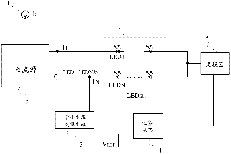
[0006] In view of this, the present invention provides a reference voltage adjustment method and circuit and its applied constant current source drive circuit to solve the problem that the current of the load LED is small, or the transistor technology in the constant current source is better and the equivalent resistance R HR Smaller, due to the fixed too high reference voltage V REF As a result, the power loss of the constant current source itself is large, thereby reducing the system efficiency of the LED, and realizing the reference voltage V of the constant current source REF Adaptive adjustment according to the change of current and resistance in the circuit

Method used


Image

  • Reference voltage regulation method and circuit as well as constant-current source driving circuit utilizing same
  • Reference voltage regulation method and circuit as well as constant-current source driving circuit utilizing same
  • Reference voltage regulation method and circuit as well as constant-current source driving circuit utilizing same

Examples


Embodiment Construction

[0040] The following will clearly and completely describe the technical solutions in the embodiments of the present invention with reference to the accompanying drawings in the embodiments of the present invention. Obviously, the described embodiments are only some, not all, embodiments of the present invention. Based on the embodiments of the present invention, all other embodiments obtained by persons of ordinary skill in the art without making creative efforts belong to the protection scope of the present invention.

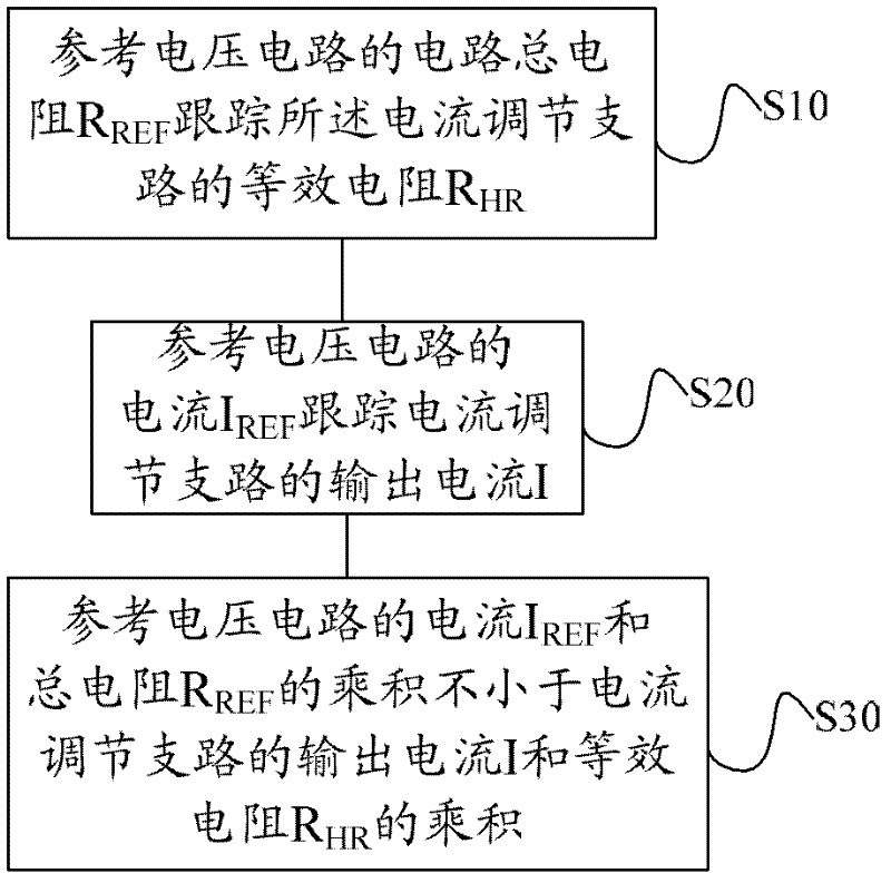
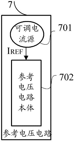
[0041] figure 2 It is a flow chart of the reference voltage regulation method of the present invention. in execution figure 2 Before the method shown, a reference voltage circuit should be preset, and the reference voltage circuit matches the current output branch in the constant current source, that is, the circuit component type, circuit component material, and circuit structure of the reference voltage circuit , which are the same as the circuit element...


PUM


Abstract

The invention discloses a reference voltage regulation method and circuit as well as a constant-current source driving circuit utilizing the same. The method comprises: the circuit total resistance RREF of a reference voltage circuit tracks the equivalent resistance RHR of a current output branch; the reference voltage circuit receives a current IREF, and the current IREF tracks the output current I of the current output branch, so that the voltage VREF (which is the product of the current IREF and the total resistance RREF) of the reference voltage circuit is not less than the voltage threshold value VHR (which is the product of the output current I and the equivalent resistance RHR) of the current output branch, and the voltage of the reference voltage circuit is used as a reference voltage of the constant-current source driving circuit, thus realizing the self-adaptive regulation of the reference voltage of the constant-current source driving circuit. By virtue of the self-adaptive regulation of the reference voltage of the constant-current source driving circuit, the problem of larger constant-current source loss is solved, and the system efficiency is improved.

Description

technical field [0001] The invention relates to the field of constant current source circuits, more specifically, to a reference voltage adjustment method and circuit for a constant current source drive circuit and a constant current source drive circuit using the same. Background technique [0002] In LED driving applications, in order to keep the LED light emission stable, a constant current source is often used to drive the LED. The constant current source used must have two characteristics: one is to maintain the output constant current characteristics as much as possible, and the other is to maintain a low self-loss, so that the system efficiency of the LED can be maintained at a high level. In order to meet the first characteristic, that is, to ensure that the output current of the constant current source is as constant as possible, the voltage value at both ends of the constant current source must meet the voltage value required by the constant current source for its ...

Claims


Application Information

Patent Timeline
IPC IPC(8): H05B37/02H05B44/00
CPCH05B33/0827H05B37/02H05B45/46H05B45/37Y02B20/30H02M3/156H02M7/217
Inventor 程帅
Owner SILERGY SEMICON TECH (HANGZHOU) CO LTD
Learn More