
Touch-control display panel

A technology of touch display panel and touch unit, which is applied in the fields of instruments, calculations, electrical digital data processing, etc., can solve the problems of error-prone and touch sensing errors, and reduce the inconsistency of read signals and good sense The effect of measuring accuracy

Inactive Publication Date: 2014-03-19
AU OPTRONICS CORP
View PDF4 Cites 0 Cited by
  • Summary
  • Abstract
  • Description
  • Claims
  • Application Information

AI Technical Summary

Problems solved by technology

However, when multiple differential driving circuit chips are used to perform the above actions, these touch units may be connected to different differential driving circuit chips through different transmission structures (such as circuit boards, wire layouts, etc.)
In this way, even when the touch display panel is not touched, the signals received by different differential drive circuit chips may not be consistent, so that the calculation process of the signal difference is easy to be wrong, resulting in touch sensing. the error

Method used


Image

  • Touch-control display panel
  • Touch-control display panel
  • Touch-control display panel

Examples


Embodiment Construction

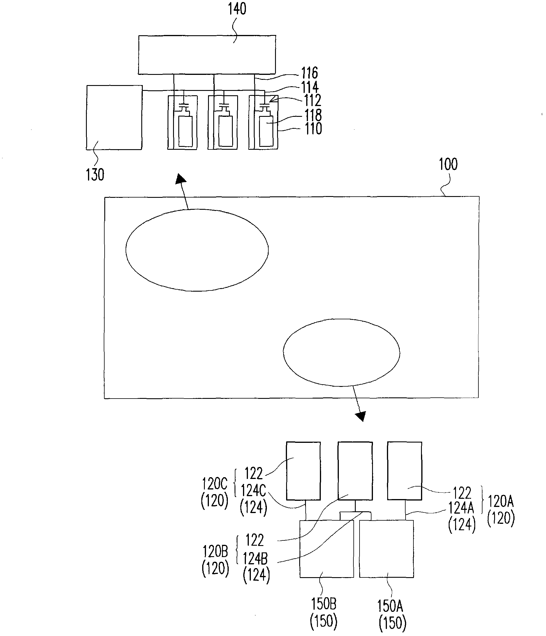
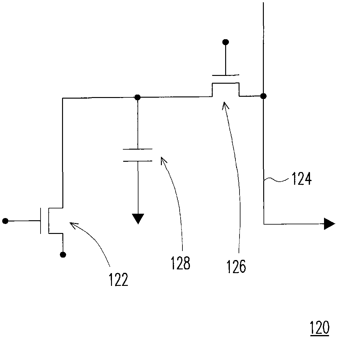
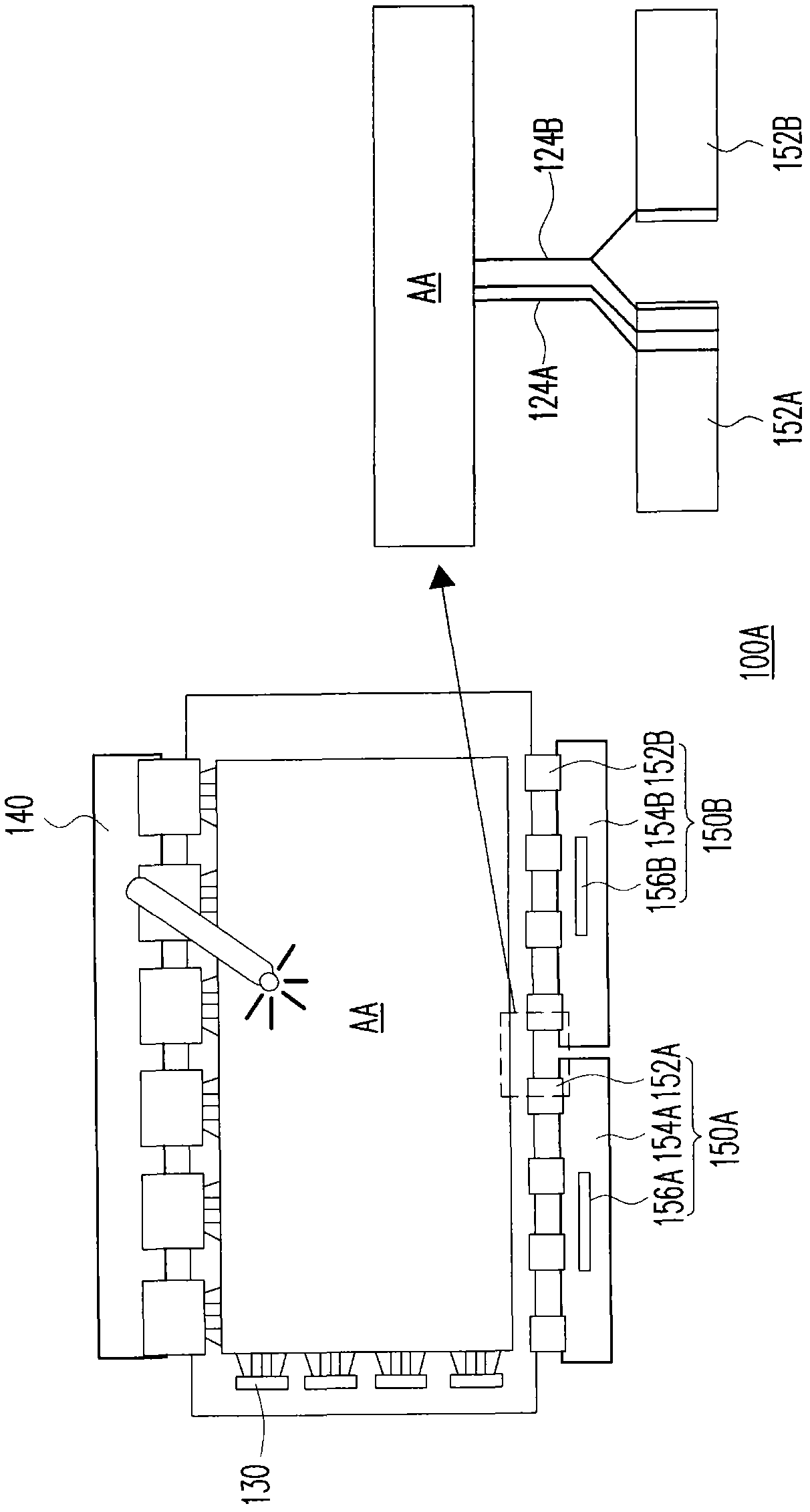
[0062] figure 1 It is a schematic diagram of a touch display panel according to an embodiment of the present invention. Please refer to figure 1 The touch display panel 100 includes at least two display units 110 , at least two touch units 120 , at least one gate driving circuit 130 , at least one data driving circuit 140 , and at least two reading circuits 150 . Each display unit 110 at least includes a switching element 112 , a gate line 114 , a data line 116 and a pixel electrode 118 , and the switching element 112 is connected to the gate line 114 , the data line 116 and the pixel electrode 118 . At least one gate driving circuit 130 is electrically connected to the gate lines 114 of each display unit 110 . At least one data driving circuit 140 is electrically connected to the data lines 116 of each display unit 110 . In addition, in order to achieve the display function, the touch display panel 100 further includes a display medium layer (not shown) disposed on the pix...


PUM


Abstract

A touch-sensing display panel includes display units, touch-sensing units, a gate driver circuit, a data driver circuit, and readout circuits. Each display unit includes a switching element, a gate line, a data line, and a pixel electrode. The switching element is connected to the gate line, the data line, and the pixel electrode. The touch-sensing units includes a first, a second, and a third touch-sensing units. Each touch-sensing unit includes a sensing element and a sensing line electrically connected to the sensing element. The gate driver circuit is electrically connected to the gate line. The data driver circuit is connected to the data line. The readout circuit includes adjacent first and second readout circuits. The sensing line of the first touch-sensing unit is connected to the first readout circuit. The sensing line of the second touch-sensing unit is connected to the first and the second readout circuits simultaneously.

Description

technical field [0001] The present invention relates to a touch display panel, and in particular to a touch display panel using differential signals to calculate touch positions. Background technique [0002] With the advancement of display technology, people can make their lives more convenient with the assistance of displays. In order to achieve the characteristics of lightness and thinness of displays, flat panel displays (FPDs) have become the current mainstream. In recent years, all kinds of electronic products are constantly moving towards the direction of easy operation, small size and large screen size, especially portable electronic products have stricter requirements on volume and screen size. Therefore, many electronic products integrate the touch-sensitive design with the display panel, so as to omit the space required for the keyboard or control keys, thereby expanding the configurable area of ​​the screen. [0003] Generally speaking, a touch display panel inc...

Claims


Application Information

Patent Timeline
Patent Type & Authority Patents(China)
IPC IPC(8): G06F3/041
CPCG06F3/044G06F3/041G06F3/0412G06F3/045G06F3/0416G06F3/04164G06F3/04166
Inventor 郑宜如徐雅玲
Owner AU OPTRONICS CORP
Learn More