
Electric louver structure

A louver structure and electric technology, which is applied to windows/doors, building components, building structures, etc., can solve the problems that users cannot temporarily control the opening and closing of louvers manually, high price, and high energy consumption, so as to achieve anti-theft and ventilation Low performance, low cost and energy consumption, and the effect of improving the structure of doors and windows

Inactive Publication Date: 2012-04-11
上海暄昉新材料有限公司
View PDF6 Cites 2 Cited by
  • Summary
  • Abstract
  • Description
  • Claims
  • Application Information

AI Technical Summary

Problems solved by technology

[0004] The existing electric shutter structure is generally driven by an external motor, and the swing of the shutter is controlled by a telescopic motor. , the user cannot temporarily manually control the opening and closing of the blinds

Method used


Image

  • Electric louver structure
  • Electric louver structure
  • Electric louver structure

Examples


Embodiment Construction

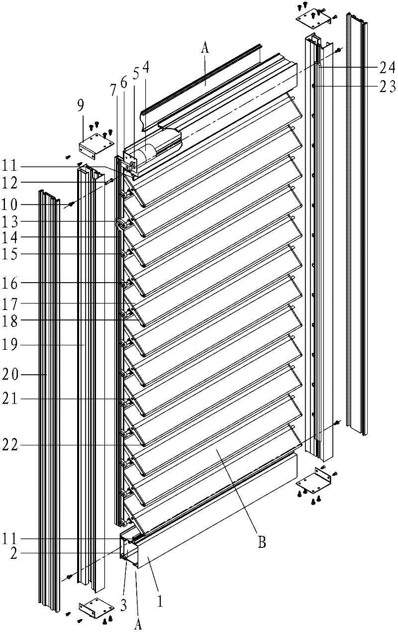
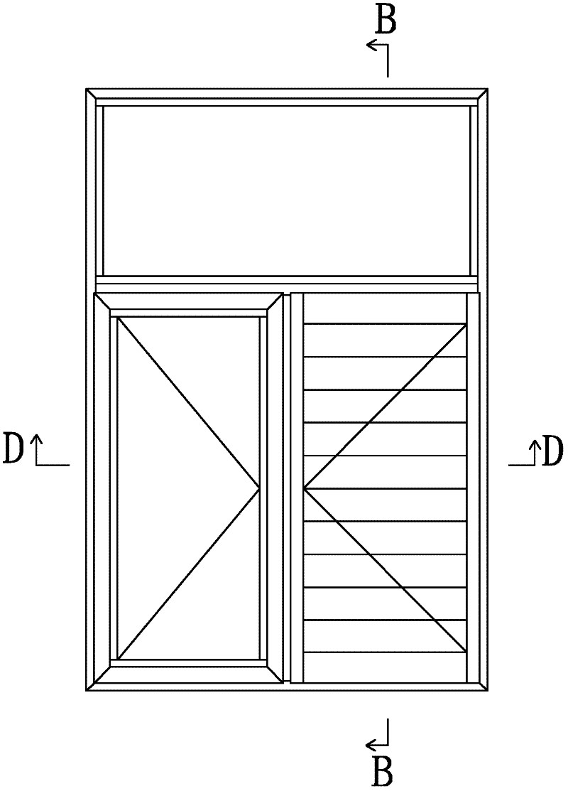
[0022] like Figures 1 to 4 As shown, the electric shutter structure of the present invention includes a window frame, a plurality of shutter assemblies B and a drive assembly that drives the shutter assemblies to swing, wherein the window frame includes two mullion assemblies arranged on both sides and two The lower horizontal frame assembly A, the two mullion assemblies are respectively used as the left and right mullion assemblies, the two horizontal frame assemblies are respectively used as the upper and lower horizontal frame assemblies, and the two ends of each louver assembly B are connected with the left and right mullion assemblies respectively. Relatively rotatable mating connection. The drive assembly includes a motor 4, a drive guide rod 14, a motor swing arm 6, a motor swing arm pin 7, a blade swing arm 13 and a blade swing arm pin 15 corresponding to the louver assembly B one by one, and the motor 4 can pass through the motor bracket 5 Installed in the upper hor...


PUM


Abstract

The invention discloses an electric louver structure comprising a louver frame, a plurality of louver assemblies and a drive assembly for driving the louver assemblies to swing, wherein the drive assembly includes a motor, a drive guide rod, a motor swinging arm as well as a motor swinging arm pin, and a blade swinging arm as well as a blade swinging arm pin; the motor is mounted in an upper transverse frame assembly; the drive guide rod is in sliding fit with a sliding groove formed in a left vertical frame assembly; the motor swinging arm pin is fixedly connected to the motor swinging arm; the motor swinging arm pin is embedded into a long hole formed on the drive guide rod and in sliding fit with the same; the motor swinging arm and a motor shaft are connected mutually in a way of limiting relative rotation therebetween; the blade swinging arm pin is fixedly connected to the drive guide rod; the blade swinging arm and the louver assemblies are connected mutually in a way of limiting relative rotation therebetween; and the blade swinging arm pin is embedded into a long hole formed on the blade swinging arm and in sliding fit with the same. The electric louver structure disclosed by the invention is more beautiful as a concealed motor is used; in addition, the drive assembly structure can realize driving by using a common micro-motor, so that both cost and energy consumption are relatively low.

Description

technical field [0001] The invention relates to a building energy-saving door and window product, and mainly relates to an electric shutter structure with a hidden motor. Background technique [0002] Since the outbreak of the world energy crisis in 1973, the prices of energy products, such as oil, have skyrocketed, forcing countries to develop energy-saving products to adapt to economic development. Now, the energy consumption of buildings in developed countries has dropped to 1 / 3-1 / 5 of that before the energy crisis. [0003] my country started building energy conservation work in the 1980s. At present, the energy consumption per unit of building in my country is 2 to 3 times that of developed countries with similar climates, the energy consumption of external windows is 1.5 to 2.2 times that of developed countries, and the air leakage rate of doors and windows is that of developed countries. 3 to 6 times of that. This shows that there is still a large gap between my coun...

Claims


Application Information

Patent Timeline
Patent Type & Authority Applications(China)
IPC IPC(8): E06B7/086
Inventor 杨志平
Owner 上海暄昉新材料有限公司
Learn More