Drill

A technology of drill bit and accommodating cavity, which is applied in the direction of drill bit, drilling equipment, earth-moving drilling and mining, etc., can solve the problems of drilling deviation, poor drilling, and dropped drilling.

Inactive Publication Date: 2012-04-04
CHINA COAL MINE CONSTR GRP
View PDF3 Cites 3 Cited by
  • Summary
  • Abstract
  • Description
  • Claims
  • Application Information

AI Technical Summary

Problems solved by technology

The drill bit of this structure has a good effect in surface soil construction, but when drilling in high-angle fractured rock formations, it is easy to cause drilling deviation and poor drilling, and in severe cases may drop the drill

Method used


Image

  • Drill
  • Drill
  • Drill

Examples


Embodiment Construction

[0019] A drill bit according to an embodiment of the present invention will be described in detail below with reference to the accompanying drawings. It should be clear that the described embodiments are only some of the embodiments of the present invention, not all of them. Based on the embodiments of the present invention, all other embodiments obtained by persons of ordinary skill in the art without creative efforts fall within the protection scope of the present invention.

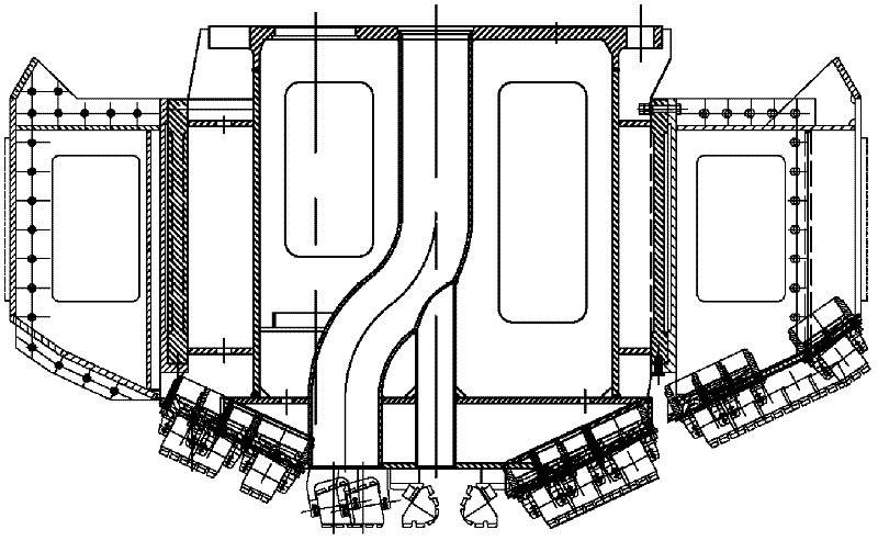
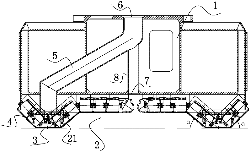
[0020] see figure 2 As shown, the drill bit of the embodiment of the present invention includes a disc-shaped cutterhead 1, the bottom of the cutterhead has a concave accommodation chamber 2, and cutting teeth 21 are arranged on the inner wall of the accommodation chamber, and the accommodation chamber The central axis of the cavity coincides with the central axis of the cutter head.

[0021] With the drill bit provided by the embodiment of the present invention, when drilling, the rock forms a conv...


PUM


Abstract

The invention discloses a drill, relates to the technical field of drilling tools, and aims to solve the problem of deflection of a drilled hole. The drill comprises a disc-shaped cutter disc, wherein the bottom of the cutter disc is provided with a concave accommodating cavity; the inner wall of the accommodating cavity is provided with cutting teeth; and the central axis of the accommodating cavity is overlapped with the central axis of the cutter disc. The drill is suitable for drilling a high-angle cracked rock formation.

Description

technical field [0001] The invention relates to the technical field of drilling tools, in particular to a drill bit used in the drilling tool. Background technique [0002] At present, the drill bit structure of the drilling method is generally a cone bit, and the cone angle is 25° to 35°. See figure 1 shown. The drill bit of this structure has a better effect in surface soil construction, but when drilling in high-angle fractured rock formations, it is easy to cause deviation of the drilling hole, poor drilling, and may drop the drilling in severe cases. Contents of the invention [0003] The invention provides a drill bit, which can prevent drilling deviation. [0004] In order to achieve the above object, embodiments of the present invention adopt the following technical solutions: [0005] A drill bit, comprising a disc-shaped cutter head, the bottom of the cutter head has a concave accommodation cavity, cutting teeth are arranged on the inner wall of the accommodat...

Claims


Application Information

Patent Timeline
Patent Type & Authority Applications(China)
IPC IPC(8): E21B10/26E21B10/42
Inventor 蔡鑫丁明
Owner CHINA COAL MINE CONSTR GRP
Why Eureka
Try Eureka