High pressure combustion method for blast-furnace hot blast stove

A hot blast stove and blast furnace technology, applied in blast furnaces, blast furnace details, blast furnace parts, etc., can solve problems such as wasting energy, and achieve the effects of improving heat storage capacity, increasing air supply temperature, and improving energy utilization rate

Inactive Publication Date: 2012-04-04
林庆霖
View PDF3 Cites 0 Cited by
  • Summary
  • Abstract
  • Description
  • Claims
  • Application Information

AI Technical Summary

Problems solved by technology

But this wastes energy

Method used


Image

  • High pressure combustion method for blast-furnace hot blast stove
  • High pressure combustion method for blast-furnace hot blast stove

Examples


Embodiment Construction

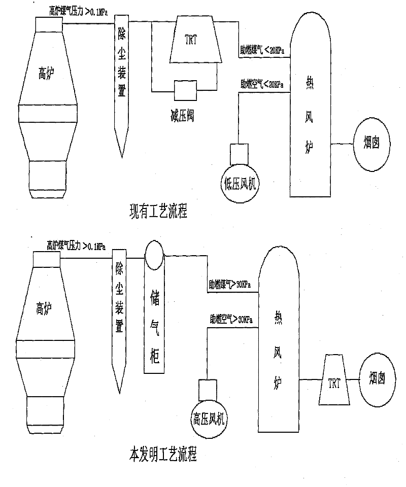
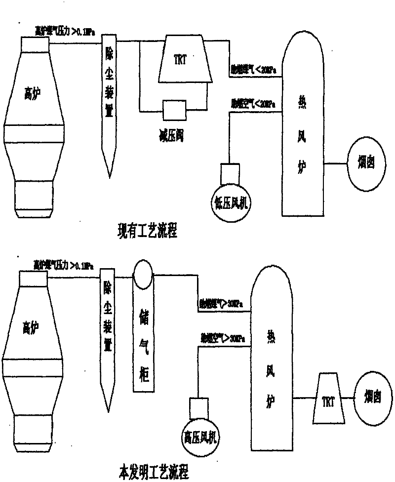
[0005] The blast furnace gas is directly sent to the hot blast stove after passing through the dust removal device and the buffer device, so as to keep the gas pressure loss as small as possible. To increase the pressure of the combustion-supporting gas when entering the hot blast stove. Depending on the size and operation mode of the blast furnace, the pressure range of the blast furnace gas is generally between 100KPa-500KPa. The combustion-supporting air is blown in by a high-pressure fan, and the inlet pressure of the combustion-supporting air is the average value of the inlet pressure of the combustion-supporting gas to ensure that the burner in the hot blast stove works normally. The exhaust gas generated by the combustion of the hot blast stove is sent to the TRT (residual pressure recovery turbine power generation device) to recover the residual pressure and waste heat.

[0006] In order to ensure the absolute safety of the hot blast stove under high pressure during c...


PUM


Abstract

The invention relates to a high pressure combustion method for a blast-furnace hot blast stove, belonging to the technical field of blast-furnace hot blast stove combustion manners. The pressure of combustion air and combustion gas in the blast-furnace hot blast stove is increased to 30-800 kPa, the content of oxygen in unit volume in the combustion air and the content of carbon monoxide in the combustion gas can be relatively increased, the vault temperature of the hot blast stove can be increased, and combustion in the hot blast stove at high pressure can provide sufficient high hot blast temperature for the blast furnace.

Description

technical field [0001] The invention belongs to the technical field of blast furnace hot blast stove combustion mode. Background technique [0002] The combustion-supporting gas of the existing blast furnace hot blast stove at home and abroad is converted into atmospheric pressure gas (5-20KPa) by blast furnace high pressure gas (100-400Kpa) after TRT or a pressure reducing valve, and then enters the hot blast stove for combustion. Due to the low calorific value of blast furnace gas, the temperature of the hot blast generated by the hot blast stove is relatively low. Although the hot blast stove adopts the addition of converter gas and oxygen enrichment, so that the temperature of the blast sent out by the hot blast stove is relatively high, and the blast temperature can reach about 1200°C, but it still cannot meet the operating needs of the blast furnace with high blast temperature and low coke ratio. The existing general situation at home and abroad: In order to meet the ...

Claims


Application Information

Patent Timeline
Patent Type & Authority Applications(China)
IPC IPC(8): C21B9/00
Inventor 林庆霖
Owner 林庆霖
Why Eureka
Try Eureka