Rear underbody for a vehicle

A body floor and rear technology, applied in the field of rear body floor, can solve the problem of large size of components and parts, and achieve the effects of reducing development cost, high torsional strength and high rigidity

Inactive Publication Date: 2012-03-21
GM GLOBAL TECH OPERATIONS LLC
View PDF0 Cites 2 Cited by
  • Summary
  • Abstract
  • Description
  • Claims
  • Application Information

AI Technical Summary

Problems solved by technology

[0004] However, the problem with this low-cost vehicle manufacture is that many of the components and parts of the next higher level vehicle are not suitable for use in smaller vehicles because they are too large

Method used


Image

  • Rear underbody for a vehicle
  • Rear underbody for a vehicle
  • Rear underbody for a vehicle

Examples


Embodiment Construction

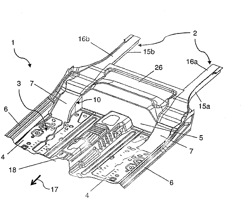
[0038] figure 1 A possible embodiment of a rear underbody 1 for a vehicle or motor vehicle, in particular a passenger car, is shown schematically. The rear underbody 1 is especially suitable for a four-seater vehicle, in particular a four-seater compact car.

[0039] The rear underbody 1 has a rear frame structure 2 and a floor structure 4 which forms a floor for a foot well 3 of the vehicle. Furthermore, the rear underbody 1 has a closure 5 delimiting the footwell 3 to the rear, which closure is formed by a so-called footboard.

[0040]Viewed in the direction of travel 17, the structures of the rear underbody 1 are arranged sequentially, the rear frame structure 2 is arranged behind the floor structure 4, wherein the floor structure 4 terminates at the footrest 5, which represents the footwell 3 the end. Viewed in the direction of travel 17 , the floor structure 4 can have, essentially in the central region, a central bracket or channel 18 which extends to the footboard 5 ...


PUM


Abstract

The invention relates to a rear underbody 1 for a vehicle with a rear frame structure 2, a floor structure 4 forming the floor for the footwell 3 of the vehicle and with a termination structure 5 delimiting the footwell 3 to the rear. According to the invention, the rear frame structure 2 extends at least partially forward and beyond the termination structure 5.

Description

technical field [0001] The invention relates to a rear underbody for a vehicle with a rear frame structure, a floor structure forming a floor for a footwell of the vehicle and a closure structure delimiting the footwell rearwardly. Background technique [0002] Such underbody panels of the body are common in vehicles, especially automobiles. Such underbody panels are often used in so-called small cars and higher class vehicles. [0003] In the cost-effective production of vehicles, in particular passenger cars, it is an aim during the development of new vehicle models that as many components and parts of the vehicle body structure as possible be able to use components and parts from the next higher level of the vehicle body. It is also an attempt to maintain an assembly sequence in the manufacture of such a vehicle that is consistent with the assembly sequence already established in the manufacture of the next higher level vehicle. This allows the vehicle to be built on th...

Claims


Application Information

Patent Timeline
IPC IPC(8): B62D25/20
CPCB62D25/2027B62D21/02
Inventor U·米尔德纳
Owner GM GLOBAL TECH OPERATIONS LLC
Why Eureka
Try Eureka