
Control system of automobile flashing unit

A technology of unit control and control system, applied in optical signals, vehicle components, signal devices, etc., can solve the problems of poor quality of trailer wiring harness, overloaded products, and uneven quality of trailers.

Inactive Publication Date: 2012-03-21
湖北安泰汽车电气系统有限公司
View PDF5 Cites 10 Cited by
  • Summary
  • Abstract
  • Description
  • Claims
  • Application Information

AI Technical Summary

Problems solved by technology

[0003] 1. The user refits the trailer at will, adding trailer bulbs, causing the product to be overloaded and burnt;
[0004] 2. The quality of trailers is uneven. Many trailer wiring harnesses are of poor quality, and the wires lack effective protection measures. Product burnt;
[0005] 3. The current flashing control unit does not have the real-time detection function of the trailer. After the trailer is removed, the main power switch must be turned off and then the product can be restarted to correctly detect the trailer status; many drivers do not understand this, and after removing the trailer, they did not turn off Power on, switch restarted, the product still indicates that the trailer has not been unloaded, causing the driver to mistakenly believe that the product is faulty
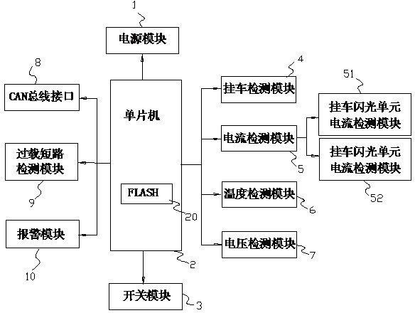
[0006] The existence of the above problems prevents the driver from normally detecting its working temperature, working voltage, and working current through the flash control unit, and cannot effectively detect the connection status between the trailer and the main vehicle, so that the product cannot work normally under complex road conditions, resulting in driving failures. security is greatly reduced
[0007] Not only that, the current flash controller lacks forward-looking research, and does not consider the realization of docking with the vehicle CAN bus control system currently being promoted

Method used


Image

  • Control system of automobile flashing unit
  • Control system of automobile flashing unit
  • Control system of automobile flashing unit

Examples


Embodiment Construction

[0031] In order to facilitate the understanding of the present invention, the present invention will be described more fully below with reference to the associated drawings. A preferred embodiment of the invention is shown in the drawings. However, the present invention can be embodied in many different forms and is not limited to the embodiments described herein. Rather, these embodiments are provided so that the disclosure of the present invention will be thorough and complete.

[0032] It should be noted that when an element is referred to as being “fixed” to another element, it can be directly on the other element or there can also be an intervening element. When an element is referred to as being "connected to" another element, it can be directly connected to the other element or intervening elements may also be present.

[0033] Unless otherwise defined, all technical and scientific terms used herein have the same meaning as commonly understood by one of ordinary skill...


PUM


Abstract

The invention relates to a control system of an automobile flashing unit, which comprises a power module, a single chip microcomputer, a switch detection module, a trailer detection module, a voltage detection module, a temperature detection module and a current detection module. The single chip microcomputer is electrically connected with the power module, the switch detection module, the trailer detection module and the voltage detection module are electrically connected with the single chip microcomputer, and the voltage detection module, the temperature detection module and the current detection module are used for detecting working states of the flashing unit in real time. The system can quickly, conveniently and effectively detect working temperature, working current and working voltage of the flashing unit and judge connection states of a trailer in real time, accordingly, a driver can judge the working states of the flashing unit more accurately, and the control system of the automobile flashing unit can meet the requirement of development of detection and control of an electric system of an integral vehicle in the future.

Description

technical field [0001] The invention belongs to the field of vehicle control, and relates to a vehicle steering control system, in particular to a steering lamp control system of a tractor and a semi-trailer, that is, an automobile flashing unit control system. Background technique [0002] Now tractors and semi-trailers are more and more widely used, and the output is also increasing. In 2010, the market sales exceeded 500,000 (only the five major automobile groups had 400,000). Due to the particularity of the structure of this type of vehicle, there is no better solution for the turn signal control of tractors and trailers. The flasher control unit used by the tractor adds a trailer detection circuit on the basis of the traditional flasher to realize the function of detecting the presence or absence of a trailer. Because the actual usage conditions of users are not considered, the failure rate in actual use is relatively high. Specifically in the following aspects: [0...

Claims


Application Information

Patent Timeline
Patent Type & Authority Applications(China)
IPC IPC(8): B60Q11/00B60Q1/38
Inventor 叶万龙
Owner 湖北安泰汽车电气系统有限公司
Learn More