
Rotating electrical machine, wind power generation system, and manufacturing method for rotating electrical machine

A technology for wind power generation systems and rotating electrical machines, applied to synchronous motors with stationary armatures and rotating magnets, wind power engines, wind power generation, etc., which can solve problems such as difficult assembly

Active Publication Date: 2016-05-18
YASKAWA DENKI KK
View PDF3 Cites 0 Cited by
  • Summary
  • Abstract
  • Description
  • Claims
  • Application Information

AI Technical Summary

Problems solved by technology

[0004] However, in the conventional generator described in the above-mentioned Japanese Patent Application Laid-Open No. 2006-6023, it is necessary to work extremely carefully during assembly, so there is a problem that assembly is very difficult and takes a long time

Method used


Image

  • Rotating electrical machine, wind power generation system, and manufacturing method for rotating electrical machine
  • Rotating electrical machine, wind power generation system, and manufacturing method for rotating electrical machine
  • Rotating electrical machine, wind power generation system, and manufacturing method for rotating electrical machine

Examples


no. 1 approach )

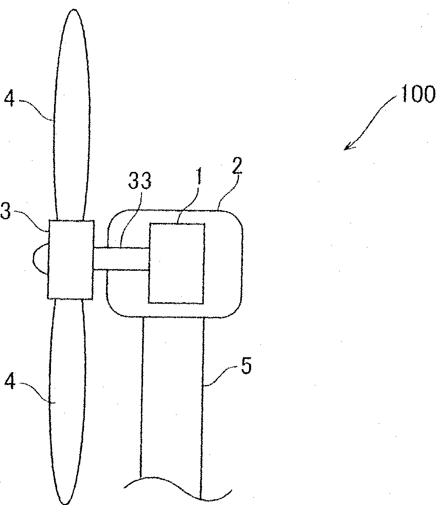
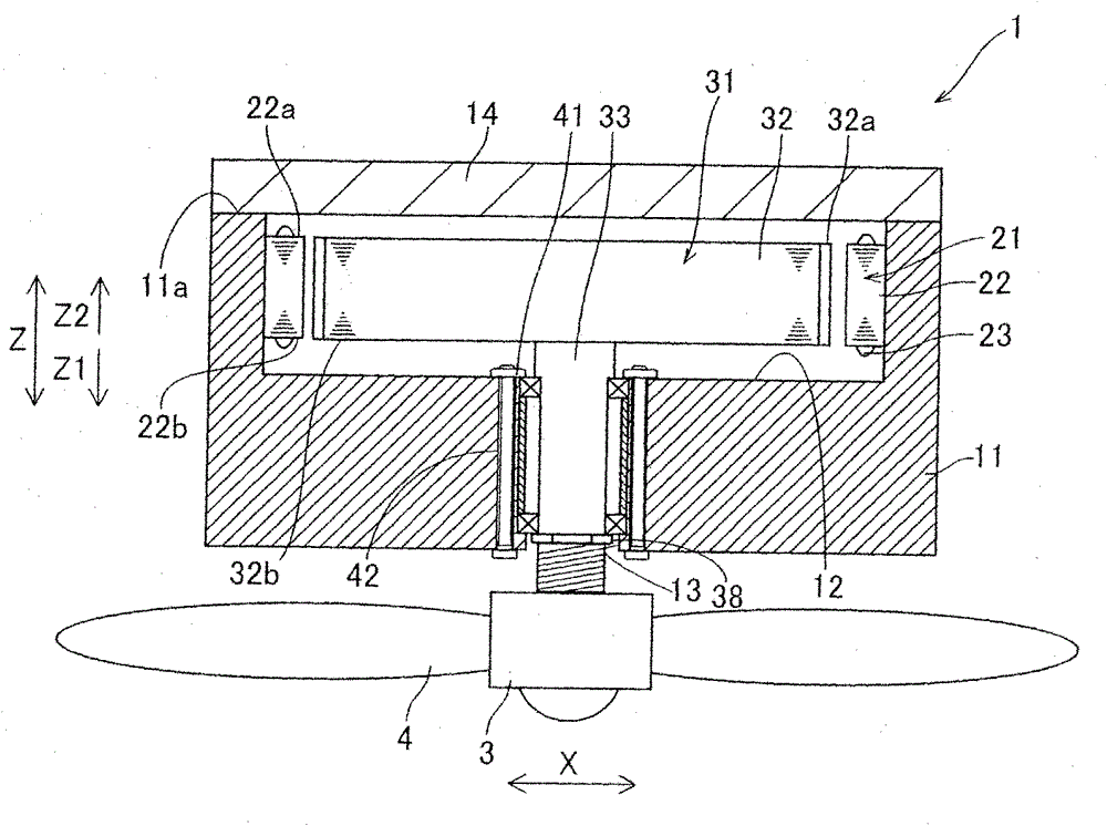
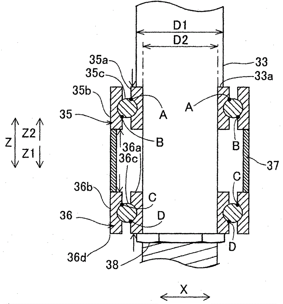
[0029] First, refer to Figure 1 to Figure 4 , the configuration of the wind power generation system 100 according to the first embodiment of the present invention will be described. In addition, in the first embodiment, an example in which the rotating electric machine of the present invention used in the wind power generation system 100 is used as the generator 1 will be described.

[0030] Such as figure 1As shown, the wind power generation system 100 is composed of a generator 1 , a nacelle 2 for accommodating the generator 1 , a rotor hub 3 , blades 4 and a tower 5 . The generator 1 is accommodated in the nacelle 2 . In addition, the rotor hub 3 is attached to a rotating shaft 33 described later of the generator 1 . In addition, a plurality of blades 4 are attached to the rotor hub 3 . Furthermore, the nacelle 2 is mounted on a tower (support column) 5 .

[0031] Such as Figure 4 As shown, the generator 1 is composed of a housing 11 , a stator 21 and a rotor 31 . ...

no. 2 approach )

[0050] Below, refer to Figure 8 and Figure 9 , the generator 1a of the second embodiment will be described. Unlike the above-mentioned first embodiment in which the first ball bearing 35 and the second ball bearing 36 are attached to the rotating shaft 33 in advance, in this second embodiment, the first ball bearing 55 and the second ball bearing 56 are attached in advance. into the rotating shaft support hole 53. In addition, the overall structure of the wind power generation system of the second embodiment is the same as that of the above-mentioned first embodiment (refer to figure 1 )same.

[0051] Such as Figure 9 As shown, the generator 1 a of the second embodiment is composed of a casing 51 , a stator 61 and a rotor 71 . The housing 51 is formed in a cylindrical shape. In addition, the housing 51 is provided with a recessed portion 52 for accommodating the stator 61 and the rotor 71 . Further, a rotating shaft support hole 53 into which the rotating shaft 73 of...


PUM


Abstract

The invention provides a rotating electrical machine, a wind power generation system and a manufacturing method of the rotating electrical machine. In this rotating electric mechanism, the length from the end portion of the rotor core on the side of the rotating shaft supporting portion to the portion that first contacts the rotating shaft supporting portion when the rotating shaft portion is inserted into the rotating shaft supporting portion is longer than that from the stator side of the rotating shaft supporting portion. The length from the end of the stator core to the end of the stator core on the side opposite to the rotating shaft support.

Description

technical field [0001] The present invention relates to a rotating electrical machine, a wind power generation system, and a method for manufacturing the rotating electrical machine, and more particularly, to a rotating electrical machine having a rotor and a stator radially opposed to the rotor, a wind power generation system, and a manufacturing method for the rotating electrical machine. Background technique [0002] Conventionally, for example, Japanese Patent Application Laid-Open No. 2006-6023 discloses a rotating electric machine having a rotor and a stator facing the rotor in the radial direction. [0003] The generator (rotary electrical machine) disclosed in the aforementioned Japanese Patent Application Laid-Open No. 2006-6023 has: a rotor; a stator facing the rotor in the radial direction; a housing (casing) for accommodating the rotor and the stator; The bearing is rotatably supported on the rotating shaft on the housing. In this generator, permanent magnets ar...

Claims


Application Information

Patent Timeline
Patent Type & Authority Patents(China)
IPC IPC(8): H02K21/14H02K21/02H02K5/16H02K15/00F03D9/00
CPCH02K7/003Y10T29/49009Y02E10/72H02K1/22H02K7/183H02K21/24
Inventor 津曲宏
Owner YASKAWA DENKI KK
Learn More