Transverse folding mechanism for empennage

A technology of horizontal folding and empennage, which is applied in the direction of fuselage, aircraft parts, transportation and packaging, etc. It can solve the problems of small torque and unsatisfactory, and achieve the effect of stable state, simple structure and guaranteed reliability

Active Publication Date: 2013-07-17
JIANGXI HONGDU AVIATION IND GRP
View PDF5 Cites 0 Cited by
  • Summary
  • Abstract
  • Description
  • Claims
  • Application Information

AI Technical Summary

Problems solved by technology

At present, most of the folding airfoils are longitudinal folding airfoils, and the empennage generally needs to be hidden inside the body, sacrificing the precious space inside the airfoil, and in some cases there is no space for installation, and the horizontal folding is adopted, and the rotating shaft of the folding airfoil is usually set At the root or middle of the airfoil, because the thickness of the empennage airfoil is relatively thin, torsion springs, springs, etc. are generally used as power sources, and the torque provided is small, which cannot meet the requirements of the empennage in place after the missile is launched in the air.

Method used


Image

  • Transverse folding mechanism for empennage
  • Transverse folding mechanism for empennage
  • Transverse folding mechanism for empennage

Examples


Embodiment 1

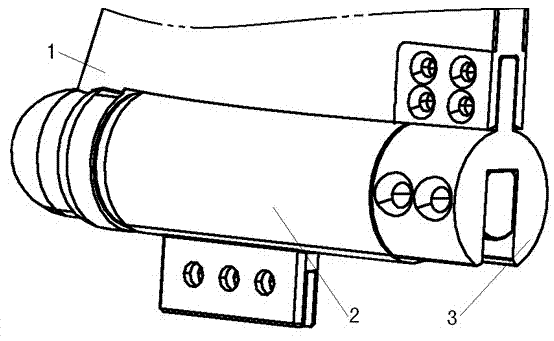
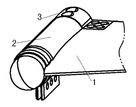
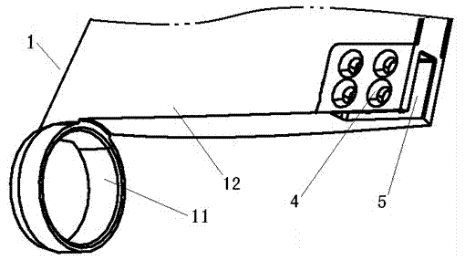
[0021] attached by Figure 1-3 The lateral folding mechanism of the empennage is composed of the empennage joint 1, the rotating actuator 2, the plug seat 3, etc. When the empennage is in the initial position, the rotating actuator 2 is provided with a shear pin, which is a locking and unlocking device for the entire mechanism, ensuring The empennage is in a fixed state, and the rotating actuating body 2 is provided with a pyrotechnic rotating actuating device, which is the power source 6 of the whole mechanism, and provides rotational torque for the empennage to be deployed in place. Its working process is as follows: after the task machine gives instructions, the rotating actuator 2 starts to work to generate a rotating torque. When the provided torque is greater than the external force that the shearing pin can bear, the shearing pin is sheared, the mechanism is unlocked, and then the rotary joint 24 Start to rotate, and then drive the plug seat 3 to rotate, and drive the e...

Embodiment 2

[0023] attached by Figure 1-3 The lateral folding mechanism of the empennage is composed of the empennage joint 1, the rotating actuator 2, the plug seat 3, etc. When the empennage is in the initial position, the rotating actuator 2 is equipped with a pin puller connected to the control of the task machine, which is the whole mechanism locked. And the unlocking device ensures that the empennage is in a fixed state, and a hydraulic pump is installed in the rotating actuating body 2, which is the power source 6 of the whole set of mechanisms and provides rotational torque for the empennage to be deployed in place. The working process is as follows: after the mission machine gives instructions, the pin puller works first, the pin puller is pulled out, the rotating actuator 2 is unlocked, and then the hydraulic pump starts to work to generate a torque, and the rotary joint 24 starts to rotate, thereby driving the plug socket 3 Rotate, drive the empennage joint 1 to rotate throug...


PUM


Abstract

The invention discloses a transverse folding mechanism for an empennage. The transverse folding mechanism which comprises an empennage joint, a rotary actuating body and a socket is characterized in that: the empennage joint is formed by an aerofoil body, a joint sleeve and a slot; one side of the aerofoil body is provided with the joint sleeve, and the other side of the aerofoil body is providedwith the slot; the slot is provided with mounting holes; one end of the rotary actuating body is a tail end; the circular shaft end of a rotary joint is connected with a power source arranged in the rotary actuating body; the power source which makes the rotary joint rotate allows the empennage joint to rotate through being driven by the socket; the rotary actuating body is provided with a locking pin A and a locking pin B which are respectively and correspondingly arranged in a pinhole of a circular shaft of the rotary joint; the locking pin B is disengaged when the rotary joint rotates, thelocking pin A is pushed into the pinhole to make the whole mechanism be in a locking state and prevent the past empennage rotation and the empennage oscillation movement when the rotary joint rotatesto a preset angle.

Description

technical field [0001] The invention relates to a folding mechanism, in particular to an empennage transverse folding mechanism. Background technique [0002] In order to reduce the hang-up space of the missile and miniaturize the launching device of the missile, it also makes the transportation and storage simple and convenient, increases the storage and transportation capacity of the storage and transportation device, and improves the combat capability of the weapon system. Deploys into place after air launch. At present, most of the folding airfoils are longitudinal folding airfoils, and the empennage generally needs to be hidden inside the body, sacrificing the precious space inside the airfoil, and in some cases there is no space for installation, and the horizontal folding is adopted, and the rotating shaft of the folding airfoil is usually set At the root or middle of the airfoil, because the thickness of the empennage airfoil is relatively thin, torsion springs, spr...

Claims


Application Information

Patent Timeline
Patent Type & Authority Patents(China)
IPC IPC(8): B64C1/26
Inventor 文革李玉亮陈雷孙英超胜永民张志强蒋若冰杨皖
Owner JIANGXI HONGDU AVIATION IND GRP
Why Eureka
Try Eureka