Eureka AIR delivers breakthrough ideas for toughest innovation challenges, trusted by R&D personnel around the world.

Optical continuous phase modulation and demodulation device

A phase modulation and modulator technology, applied in the field of optical continuous phase modulation methods and devices, can solve the problems of response speed limitation, system transmission capacity limitation, difficult high-speed modulation, etc.

Inactive Publication Date: 2013-08-14
HUAZHONG UNIV OF SCI & TECH
View PDF5 Cites 0 Cited by
  • Summary
  • Abstract
  • Description
  • Claims
  • Application Information

AI Technical Summary

Problems solved by technology

However, this internal modulation method is difficult to achieve high-speed modulation. First, due to the limitation of the response speed of the semiconductor laser itself, and second, this modulation method is accompanied by frequency chirp, which broadens the output signal spectrum and limits the transmission capacity of the system.

Method used


Image

  • Optical continuous phase modulation and demodulation device
  • Optical continuous phase modulation and demodulation device
  • Optical continuous phase modulation and demodulation device

Examples


Embodiment Construction

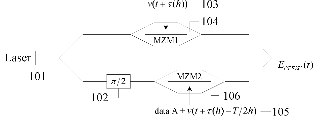
[0029] The principle of optical CPFSK modulation to realize arbitrary modulation index is as follows: figure 1 As shown, it is divided into upper and lower arms for modulation, the upper arm modulation produces the in-phase component of the CPFSK signal, and the lower arm modulation produces the quadrature component of the CPFSK signal.

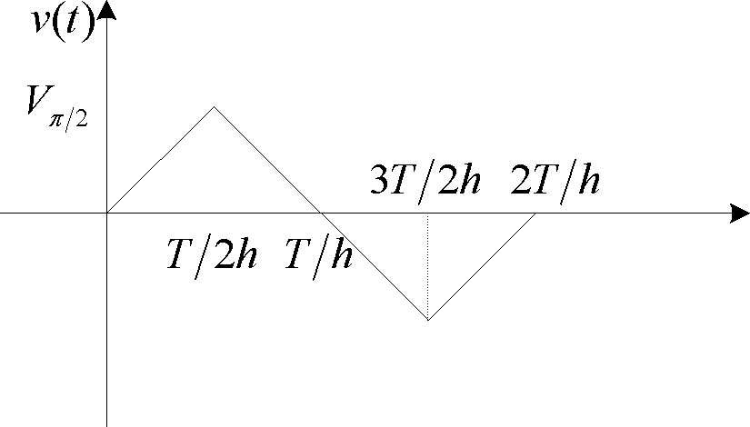
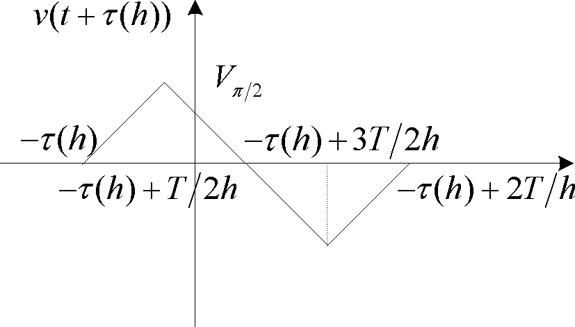
[0030] The laser light source Laser 101 emits an optical carrier, and the optical carrier is divided into upper and lower branches during modulation. The π / 2 phase shifter 102 is used on the lower branch to generate a π / 2 phase shift, and the modulated signals 103 and 105 are respectively added to On MZM1 104 and MZM2 106, the in-phase component of the modulation signal of the upper arm to be realized is

[0031] E up ( t ) = | E 0 | e j 2 ...


PUM


Abstract

The invention relates to a modulation method and a modulation device by which optical continuous phase frequency shift keying (CPFSK) with any modulation index can be realized. The device comprises a modulation part and a demodulation part, wherein the modulation part is implemented by using a two-arm structure of a mach zehnder interferometer (MZM), and a phase continuity mode is implemented by controlling the time delay of an input waveform. The invention can provide a modulation-index variable optical CPFSK method and a modulation-index variable optical CPFSK device, by which an optical CPFSK signal with constant envelope, continuous phases and any modulation index can be generated, thereby overcoming a nonlinear effect in an optical transmission process, and improving the dispersion tolerance and the PMD (polarization mode dispersion) tolerance.

Description

technical field [0001] The invention belongs to the field of digital modulation in the field of high-speed optical fiber communication, and in particular relates to an optical continuous phase (CPFSK) modulation method and device. Background technique [0002] The research on signal modulation format is a hot spot in the field of optical communication. The improvement of transmission performance of new modulation format has attracted people's attention, especially in suppressing nonlinear effects, improving dispersion tolerance and polarization mode dispersion (PMD) tolerance. Good results have been achieved. In the optical fiber communication system, the continuous light wave or light pulse train emitted by the light source does not carry information and can only be used as a carrier of information. The optical carrier signal is a signal related to the polarization direction, signal amplitude, carrier frequency, and carrier phase. If any one of the four quantities is selec...

Claims


Application Information

Patent Timeline
Patent Type & Authority Patents(China)
IPC IPC(8): H04L27/18G02F2/00
Inventor 杨彩虹黄本雄邹宁杨洋
Owner HUAZHONG UNIV OF SCI & TECH
Why Eureka
Eureka Blog
Learn More