
Novel pneumatic mechanical claw

A mechanical claw, a new technology, applied in the field of mechanical devices, can solve the problems of high cost, limited application range, low technical content, etc., and achieve the effect of simple structure and convenient use

Inactive Publication Date: 2012-02-15
李阳阳
View PDF5 Cites 24 Cited by
  • Summary
  • Abstract
  • Description
  • Claims
  • Application Information

AI Technical Summary

Problems solved by technology

[0002] In modern industry, the mechanization and automation of the production process has become a prominent theme. In the machining and injection molding industries, many stations are for picking up objects. This operation is generally simple and low-tech, and it is even difficult to find an operation. Workers use manipulators due to the high repeatability. At present, many pick-up manipulators have been designed to meet this demand, including hydraulic, pneumatic and electric. Most of them are complicated in structure, difficult to manufacture, high in cost and limited in application range

Method used


Image

  • Novel pneumatic mechanical claw
  • Novel pneumatic mechanical claw
  • Novel pneumatic mechanical claw

Examples


Embodiment Construction

[0015] The present invention will be further described below in conjunction with the accompanying drawings and embodiments.

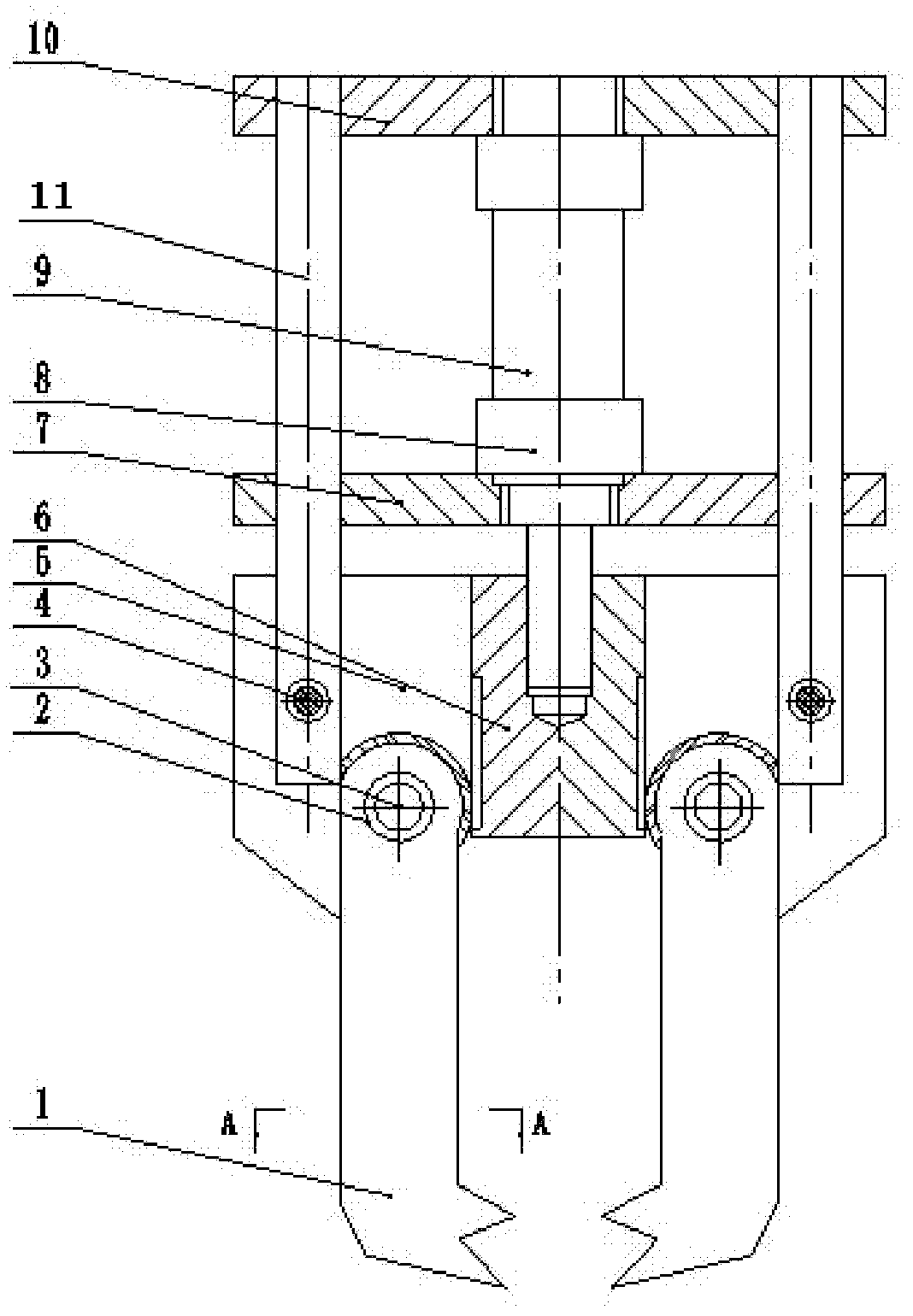
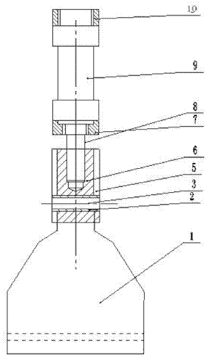
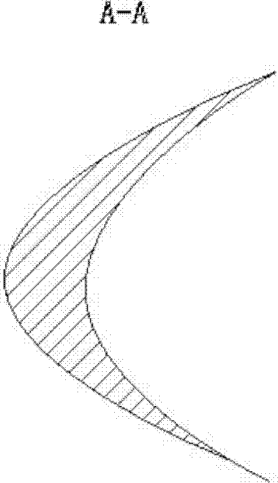
[0016] Such as figure 1 , figure 2 , image 3 As shown, the connecting plate 11 of the present invention is connected with the fixed plate 5 by fastening screws 4, and the pneumatic cylinder 9 is installed in the fixed cylinder 8 of the connecting plate 7, the upper guide plate 10 and the lower guide plate 7, and the telescopic shaft of the pneumatic cylinder 9 is connected with the fixed The rack 6 in the plate 5 is connected to drive the rack 6 to move up and down. One end of the rack 6 and the finger 1 is connected by a rack and pinion. The rack 6 drives the finger 1 to rotate around the mandrel 3, and the sliding sleeve 2 acts as an auxiliary rotation. When the pneumatic cylinder moves downward, it tightens the workpiece, and when it moves upward, it relaxes the workpiece.

[0017] Although the specific implementation of the present invention ha...


PUM


Abstract

The invention discloses a novel pneumatic mechanical claw. The novel pneumatic mechanical claw comprises a fixing plate, a finger, a guide mechanism and a pneumatic cylinder, wherein the finger is mounted on the fixing plate, a lower end of a connecting plate in the guide mechanism is fixed on the fixing plate through a fastening bolt, a rack is embedded in the middle part of the fixing plate, a pneumatic cylinder telescopic shaft is connected with the rack in the fixing plate, one end of the finger is provided with a round hole in which a sliding sleeve is arranged, the finger is connected with the fixing plate by penetrating a mandrel through the round hole, the same end is provided with an external circle coaxial with the round hole, the external circle is provided with a plurality of tooth, and the toot and the rack in the fixing plate are in gear-rack connection; the guide mechanism comprises the connecting plate, an upper guide plate and a lower guide plate, the middle and two ends of each of the upper guide plate and the lower guide plate are respectively provided with holes; the middle holes are all equipped with a fixed column, the connecting plate is connected with the upper guide plate and the lower guide plate after penetrating through the holes at two ends. The work piece is tightened and loosened by using the mechanical principle; and the novel pneumatic mechanical claw is mechanical and automatic in production, time-saving and labor-saving, simple in structure and convenient for use.

Description

technical field [0001] The invention relates to a mechanical device, in particular to a novel pneumatic mechanical gripper. Background technique [0002] In modern industry, the mechanization and automation of the production process has become a prominent theme. In the machining and injection molding industries, many stations are for picking up objects. This operation is generally simple and low-tech, and it is even difficult to find an operation. Workers use manipulators due to the high repeatability. At present, many pick-up manipulators have been designed to meet this demand, including hydraulic, pneumatic and electric. Most of them are complicated in structure, difficult to manufacture, high in cost and limited in application range. Contents of the invention [0003] The object of the present invention is to solve the above problems and provide a novel pneumatic mechanical gripper, which has the advantages of simple structure and convenient use. [0004] In order to ...

Claims


Application Information

Patent Timeline
Patent Type & Authority Applications(China)
IPC IPC(8): B25J15/08
Inventor 李阳阳曹学友刘兵郭庆省刘帅刘烟台单波申超
Owner 李阳阳
Learn More