Gear shifting handle

A technology for shifting handles and gears, applied to components with teeth, belts/chains/gears, mechanical equipment, etc., can solve problems such as complexity, inflexibility, and complex structure, and achieve simple mechanical structure and reasonable design , Increase the effect of application range

Active Publication Date: 2012-02-08
SPECIAL VEHICLE TECH CENT OF HUBEI AEROSPACE TECH RES INST
View PDF6 Cites 3 Cited by
  • Summary
  • Abstract
  • Description
  • Claims
  • Application Information

AI Technical Summary

Problems solved by technology

[0002] At present, most of the automatic transmission shift levers of vehicles adopt gear positions distributed on both sides of the shift lever movement groove, and each gear position has a corresponding groove, so as to ensure that the shift lever is in each gear. The position can be well restricted, the shift lever is mechanical, the mechanical locking and unlocking makes the movement of the shift handle solidified, there is no flexibility, and it can only be locked in the corresponding gear position. If it is necessary to realize multi-gear locking and unlocking, the mechanical structure of the shift handle will be very complicated.
For example, the invention patent with the patent number CN201110025439.6 discloses a shift lever device, in which the adsorption member or switching member is set immovable. In this shift lever device, even if the magnet is set immovable, the first link And the yoke plate can slide, and the second link can be rotated relative to the first link, and switch the attraction and non-adsorption of the magnet to the yoke plate, thereby being able to switch the gear lever from the "P" shift position to " The structure of the prevention and permission of the operation of the R” shift position is quite complicated

Method used


Image

  • Gear shifting handle
  • Gear shifting handle
  • Gear shifting handle

Examples


Embodiment Construction

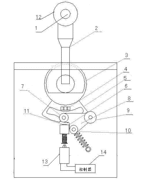
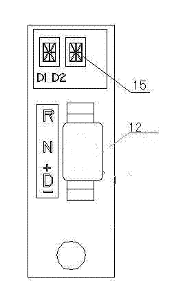
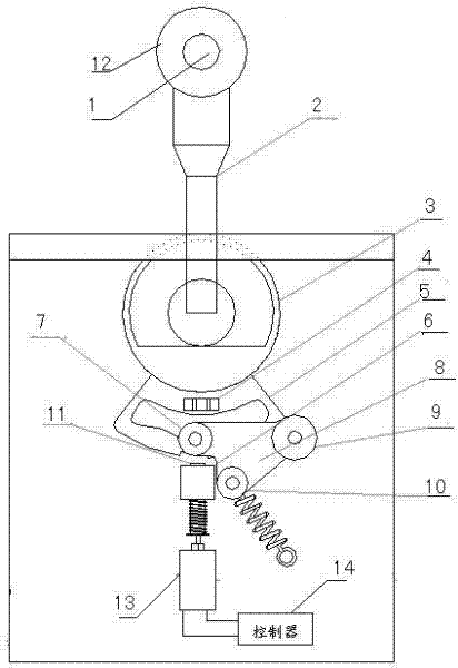
[0013] a shift lever such as figure 1 and figure 2 As shown, it includes a controller 14 and an operating mechanical unit. The controller 14 issues control instructions to assist in controlling the operation of the operating mechanical unit; the operating mechanical unit includes an unlock button 1, an operating rod 2, a round handle block 3, a magnet block 4, and a gear position Limiting block 5, fixed block 6, gear position limiting spring block 8, iron post 11, operating rod handle 12, electromagnet 13. Among them, the three ends of the gear limit spring block are respectively provided with a fixed wheel 9, a spring tension wheel 10, and an embedded wheel 7; On the lower end side of the operating rod 1 is connected with the round handle block 3, the center of the round handle block 3 is fixed, the gear limit block 5 and the round handle block 3 are connected together, the gear limit block 5 has three grooves, the corresponding The handle 12 of the operating rod is provid...


PUM


Abstract

The invention belongs to the technical field of a vehicle automatic transmission gearshift, and in particular relates to a gear shifting handle. The gear shifting handle comprises a controller and an operating machine unit, wherein a fixed pulley, a spring tension wheel, and an embeded wheel are arranged at three ends of a gear limiting move spring block in the operating machine unit; the upper end of an operating arm is provided with an operating arm grab handle, an unlock button is arranged on the operating arm grab handle, one side of the lower end of the operating arm is connected with a circle handle block, and a gear limiting block is connected with the circle handle block; the gear limiting block is provided with three grooves, a magnet block is fixed on the gear limiting block, and the gear limiting move spring block is arranged on the lower end of the gear limiting block; the embedded wheel is embedded in the gear limiting block, and the fixed pulley is used for fixing one end of the gear limiting block; and an iron prop is arranged below the gear limiting move spring block, and the lower end of the iron prop is connected with an electromagnet. The gear shifting handle provided by the invention has the advantages of simple mechanism unit structure, reasonable design, and practical function.

Description

technical field [0001] The invention belongs to the technical field of gear shifting of vehicle automatic transmissions, and in particular relates to a gear shift handle. Background technique [0002] At present, most of the automatic transmission shift levers of vehicles adopt gear positions distributed on both sides of the shift lever movement groove, and each gear position has a corresponding groove, so as to ensure that the shift lever is in each gear. The position can be well restricted, the shift lever is mechanical, the mechanical locking and unlocking makes the movement of the shift handle solidified, there is no flexibility, and it can only be locked in the corresponding gear position. If it is necessary to realize multi-gear locking and unlocking, the mechanical structure of the shift handle will be designed very complicated. For example, the invention patent with the patent number CN201110025439.6 discloses a shift lever device, in which the adsorption member or...

Claims


Application Information

Patent Timeline
Patent Type & Authority Applications(China)
IPC IPC(8): F16H59/10F16H63/34
Inventor 桑任仲李兴龙周谊张波
Owner SPECIAL VEHICLE TECH CENT OF HUBEI AEROSPACE TECH RES INST
Why Eureka
Try Eureka