
Throwing robot with changeable shape

A robotic and variable technology, applied in the field of robotics, can solve problems such as narrow observation range, robot damage, and low camera line of sight height, and achieve the effect of improving sight range, flexible movement ability, and expanding reconnaissance space

Active Publication Date: 2012-02-01
昆山市工业技术研究院有限责任公司
View PDF6 Cites 10 Cited by
  • Summary
  • Abstract
  • Description
  • Claims
  • Application Information

AI Technical Summary

Problems solved by technology

But the basic structure of existing throwing robot can only guarantee that when the falling ground is flat ground, the kinematic device of robot could first contact with the ground; damaged by lack of cushioning
At the same time, due to the small size of the micro-robot, the camera carried by it has a very low line of sight and a narrow observation range.

Method used


Image

  • Throwing robot with changeable shape
  • Throwing robot with changeable shape
  • Throwing robot with changeable shape

Examples


Embodiment Construction

[0036] The present invention will be specifically introduced below in conjunction with the accompanying drawings and specific embodiments.

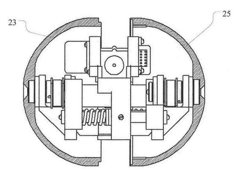
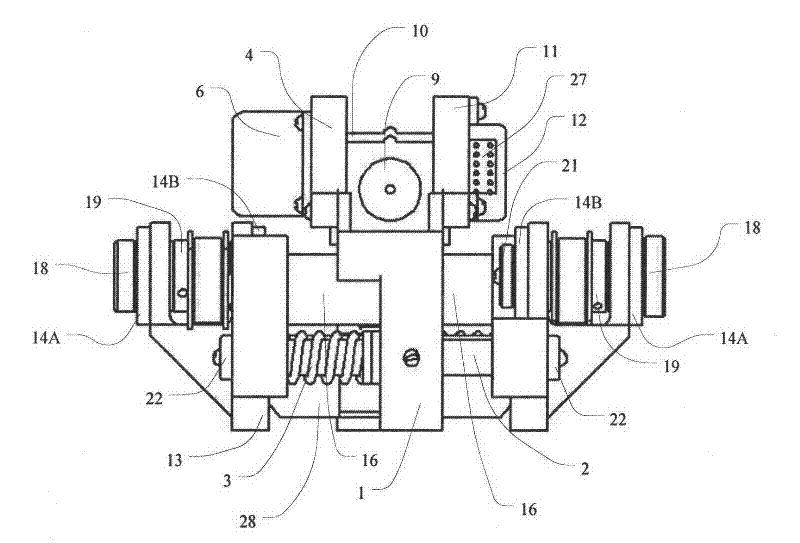
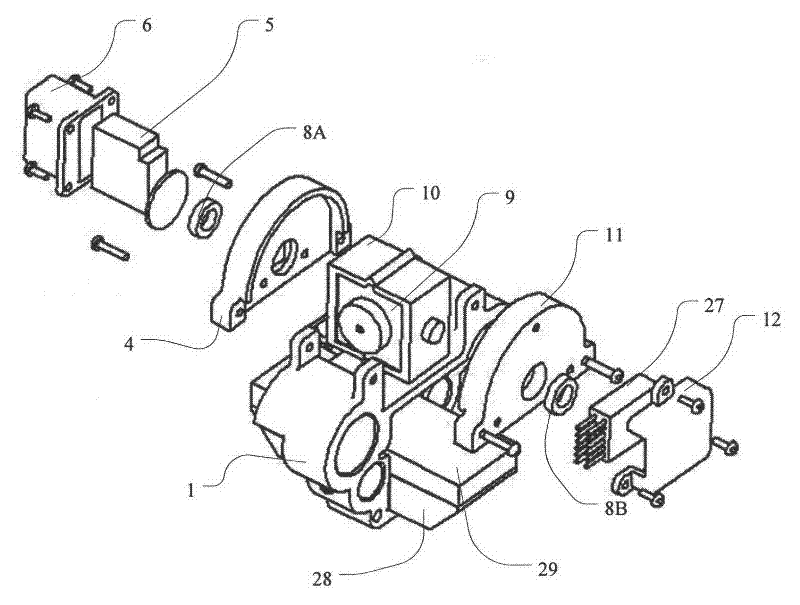
[0037] refer to figure 1 , figure 2 As shown, a variable shape throwing robot of the present invention mainly includes three parts: a shell part, an actuator part, a camera part, and a power control part; In order to make the field of view of the camera 9 good, the camera part is fixed above the actuator part.

[0038] Such as figure 1 As shown in , wherein the shell part is two half-shells 23, 25, they should be left-right symmetric, in order to enable them to rotate and travel under the drive of the wheel shaft 18 after they are opened, the two half-shells 23, 25 are all axisymmetric The semi-closed structure of the shape, its axis of symmetry is arranged horizontally and coincides with the axis of the wheel shaft 18. As a preferred solution, the two half-shells 23, 25 are hemispherical shells. In addition, they can also be semi-ellip...


PUM


Abstract

The invention discloses a throwing robot with a changeable shape, comprising a housing part, wherein the housing part comprises two symmetrical semi-housings, and the semi-housings respectively have a semi-hermetic structure with an axisymmetric shape. The throwing robot is characterized by further comprising an actuating mechanism part, a camera part and a power control part arranged in the housing part; and the two semi-housings are respectively provided with a locking part which is relatively rotated to be opened or closed, and the camera part is fixedly connected above an actuating connection part. The throwing robot has the beneficial effects that a plurality of important inner structures are protected in an inner part by the housing part of the robot, so that the housing part of therobot is always firstly contacted with the ground regardless of falling angles, therefore, the inner structures of the robot can not be damaged; the shape of the robot is changed to the structure of a two-wheel vehicle after the robot falls on the ground, so that the robot is flexible in motion capacity; and the pitching angle of the camera is adjusted by a steering engine, so that the sight linerang of the camera carried by the robot is improved, and the scouting space of the robot is enlarged.

Description

technical field [0001] The invention relates to a robot, in particular to a miniature throwable and deformable robot. Background technique [0002] At present, the existing throwing robots generally adopt the method of ensuring that the moving device first contacts with the ground as a buffer to reduce the impact force of the robot when it falls, so as to ensure that the robot will not be damaged by the impact force. But the basic structure of existing throwing robot can only guarantee that when the falling ground is flat ground, the kinematic device of robot could first contact with the ground; Damaged due to lack of cushioning. At the same time, due to the small size of the micro-robot, the camera it carries has a very low line of sight and a narrow observation range. Contents of the invention [0003] In order to solve the deficiencies of the prior art, the object of the present invention is to provide a deformable throwing robot that can protect the internal structur...

Claims


Application Information

Patent Timeline
Patent Type & Authority Applications(China)
IPC IPC(8): H04N5/225B62D57/02
Inventor 程胜刘荣渠源刘飞肖飞雨王鲁单张建伟
Owner 昆山市工业技术研究院有限责任公司
Learn More