Medical powered fret saw

A technology of power wire and wire saw, which is applied in the field of medical power wire saw, which can solve problems such as unbalanced force, inaccurate sawing, and unstable direction, so as to achieve stable cutting direction, uniform force on bones, and reduce the pain of patients.

Active Publication Date: 2014-01-01
BEIJING MONTAGNE MEDICAL DEVICE
View PDF7 Cites 0 Cited by
  • Summary
  • Abstract
  • Description
  • Claims
  • Application Information

AI Technical Summary

Problems solved by technology

[0002] In the prior art, medical wire saw cutting is usually operated by manpower, which has the disadvantages of large saw swing, manual labor, unbalanced force, unstable direction, and inaccurate sawing.
Therefore, the present invention provides a power wire saw, the power wire saw is a power device for driving the wire saw blade to reciprocate, the use of the power wire saw can save manpower, overcome the above unbalanced force, unstable direction, etc. shortcoming

Method used


Image

  • Medical powered fret saw
  • Medical powered fret saw
  • Medical powered fret saw

Examples


Embodiment 1

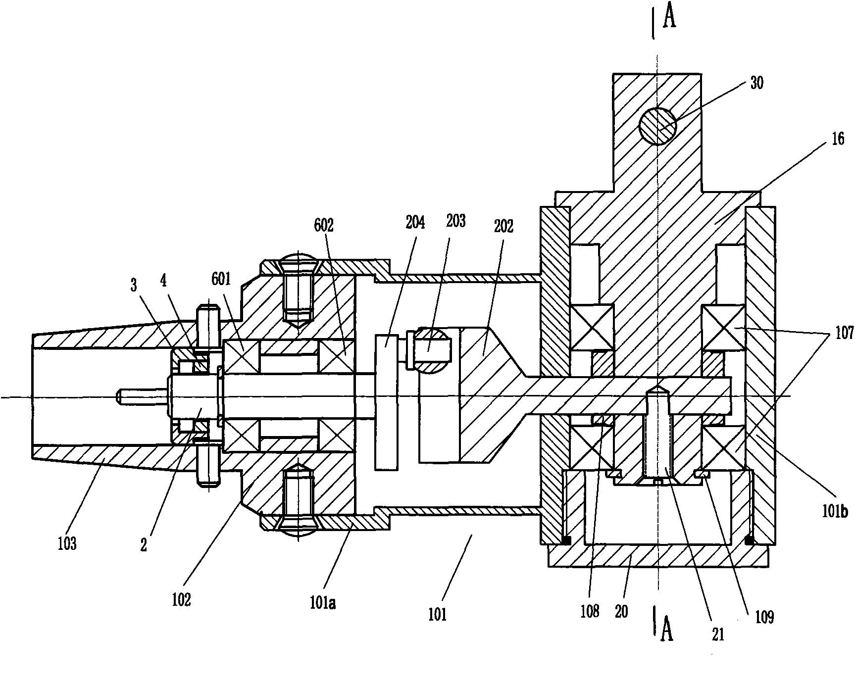
[0022] Such as figure 1 , 1a -1b and figure 2 As shown in , the power jigsaw includes a casing 1, the internal structure of the casing is sequentially, a power input shaft 2, a swing device and a swing head 16, wherein the swing device includes: an eccentric shaft 204 and a swing fork 202, and the position of the swing head is set as front end.

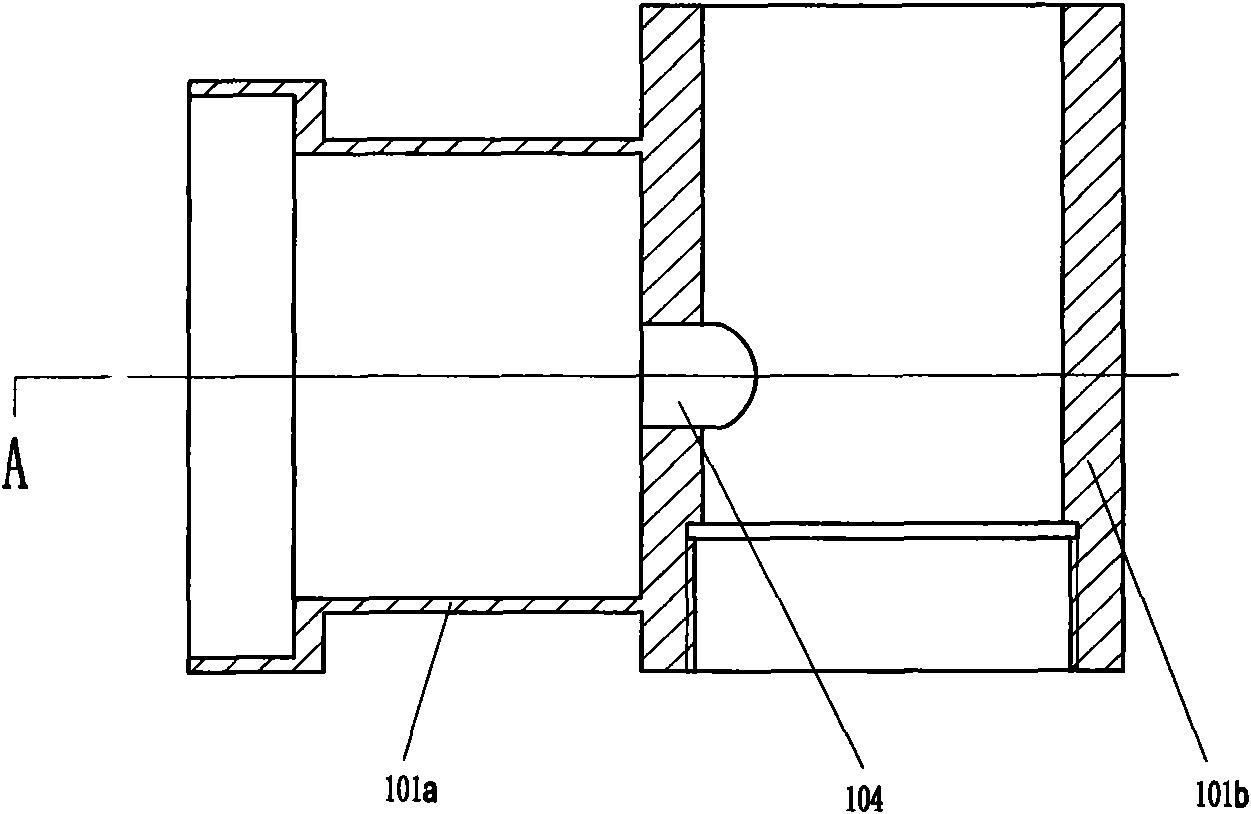
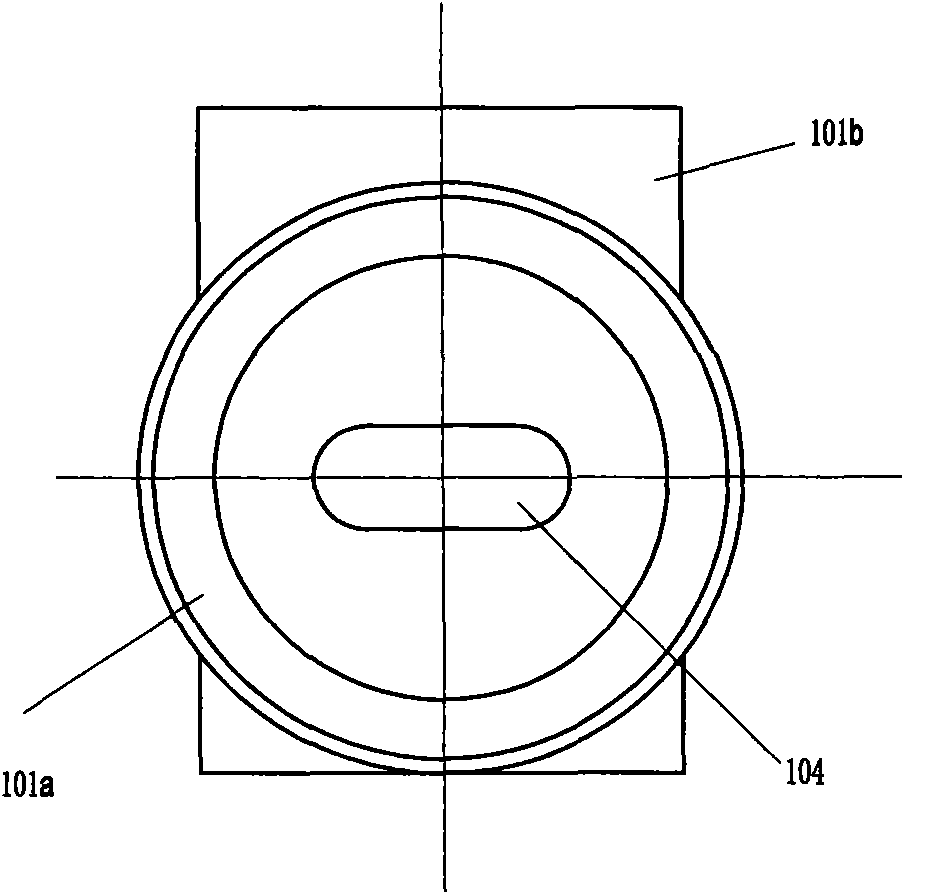
[0023] The casing 1 includes two parts, a connecting sleeve 102 and a housing 101. The rear end of the connecting sleeve 102 has a conical quick-fit joint 103; the power input shaft 2 is installed in the connecting sleeve 102, and the input end of the power input shaft 2 is arranged on the quick-fit Inside the connector 103. The eccentric shaft, the swing fork and the swing head are arranged in the housing 101 . The housing 101 includes two fixedly connected barrel structures 101 a, 101 b. A part of the swing head 16 protrudes from the housing 101 . The connection sleeve 102 and the housing 101 are fixedly connected by screws.

...

Embodiment 2

[0027] Such as image 3 As shown, compared with Embodiment 1, this embodiment adds a speed change mechanism between the power input shaft 2 and the eccentric shaft. a planetary gear 403. The central gear 402 is installed on the front end of the power input shaft, and drives the central gear 402 to rotate through the power input shaft, and then drives the three planetary gears 403 to rotate. In this embodiment, the rear end of the eccentric wheel is connected to the front end of the output shaft 201 , and the rear end of the output shaft 201 is connected to the three planetary gears 403 through three pins 404 .

[0028] When in use, the external power device drives the power input shaft 2 to rotate, and after being decelerated by the speed change mechanism 4, the power output shaft 201 drives the eccentric shaft to rotate.

[0029] In this embodiment, the planetary carrier 401, as a part of the casing, is arranged between the front housing 101 and the connecting sleeve 102, a...


PUM


Abstract

A medical powered fret saw comprises a shell, a power input shaft, a swinging mechanism, a swinging head and a fret saw-supporting mechanism; the front end of the power input shaft is connected with the swinging mechanism, and supplies power to the swinging mechanism; the front end of the swinging mechanism is firmly connected with the swinging head, the swinging head is extended out from the front end of the shell, the fret saw-supporting mechanism is arranged on the part of the swinging head, which is extended out of the shell, and the fret saw-supporting mechanism is used for supporting a fret saw; the swinging mechanism comprises an eccentric shaft and a swinging fork, the eccentric shaft is fixed on the front end of the power input shaft, and the swinging fork is connected with the eccentric shaft. During operation, the eccentric shaft is driven by the power input shaft to revolve, the swinging fork is driven by the eccentric shaft to swing back and forth, the swinging head arranged on the front end of the swinging fork is driven by the swinging fork to swing back and forth, and thereby the fret saw arranged on the fret saw-supporting mechanism is driven to reciprocate.

Description

technical field [0001] The patent of the present invention relates to a medical power wire saw. Background technique [0002] In the prior art, medical wire saw cutting is usually performed by manpower, which has disadvantages such as large saw swing, manual labor, unbalanced force, unstable direction, and inaccurate sawing. Therefore, the present invention provides a power wire saw, the power wire saw is a power device for driving the wire saw blade to reciprocate, the use of the power wire saw can save manpower, overcome the above unbalanced force, unstable direction, etc. shortcoming. Contents of the invention [0003] The purpose of the present invention is to provide a power drive device for a wire saw, which can save manpower when cutting with a wire saw. [0004] A medical power wire saw, comprising a casing, and a power input shaft, a swing device, a swing head, and a wire saw support device sequentially arranged in the casing; the front end of the power input sh...

Claims


Application Information

Patent Timeline
Patent Type & Authority Patents(China)
IPC IPC(8): A61B17/14
Inventor 周袭明
Owner BEIJING MONTAGNE MEDICAL DEVICE
Why Eureka
Try Eureka