
Binocular telescope and adjustment method for binocular telescope

A technology of binoculars and focal length adjustment, applied in the field of optical instruments, can solve the problems of high production cost, complex use environment, large matching area, etc., and achieve the effects of easy operation, convenient adjustment of diopter and focal length.

Active Publication Date: 2013-08-07
冯影
View PDF4 Cites 0 Cited by
  • Summary
  • Abstract
  • Description
  • Claims
  • Application Information

AI Technical Summary

Problems solved by technology

[0002] In the prior art, the adjustment of the binoculars usually includes diopter adjustment and focus adjustment. The diopter adjustment is usually done by rotating the eyepiece or the objective lens, and then moving the eyepiece or the objective lens to complete the diopter adjustment. The focus is adjusted by turning the middle adjusting hand wheel The diameter of the matching surface of the moving part of the eyepiece tube is 18mm-28mm, and the length is 10mm-28mm. The matching area is very large, and it is difficult and laborious to adjust.
[0003] On the other hand, in the adjustment method of rotating the eyepiece, due to the large rotating area, in order to ensure the use effect of the binoculars, higher processing accuracy is required, which increases the production cost of the binoculars; especially the current environment for using the binoculars is complicated. , on the basis of ensuring the diopter adjustment function, most of them need to have a waterproof function, and the rotation of the eyepiece or objective lens is not conducive to waterproofing. Therefore, the manufacturing difficulty of the telescope is increased, and the production cost is higher.

Method used


Image

  • Binocular telescope and adjustment method for binocular telescope
  • Binocular telescope and adjustment method for binocular telescope

Examples


Embodiment Construction

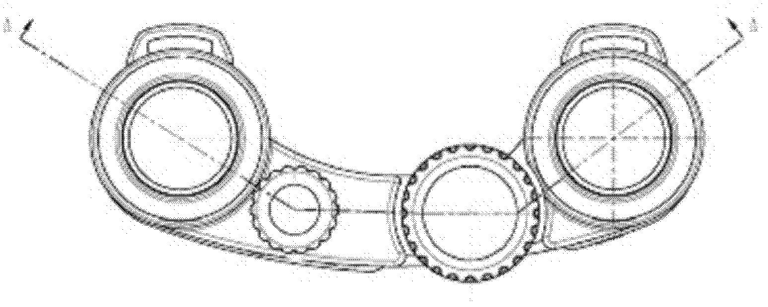
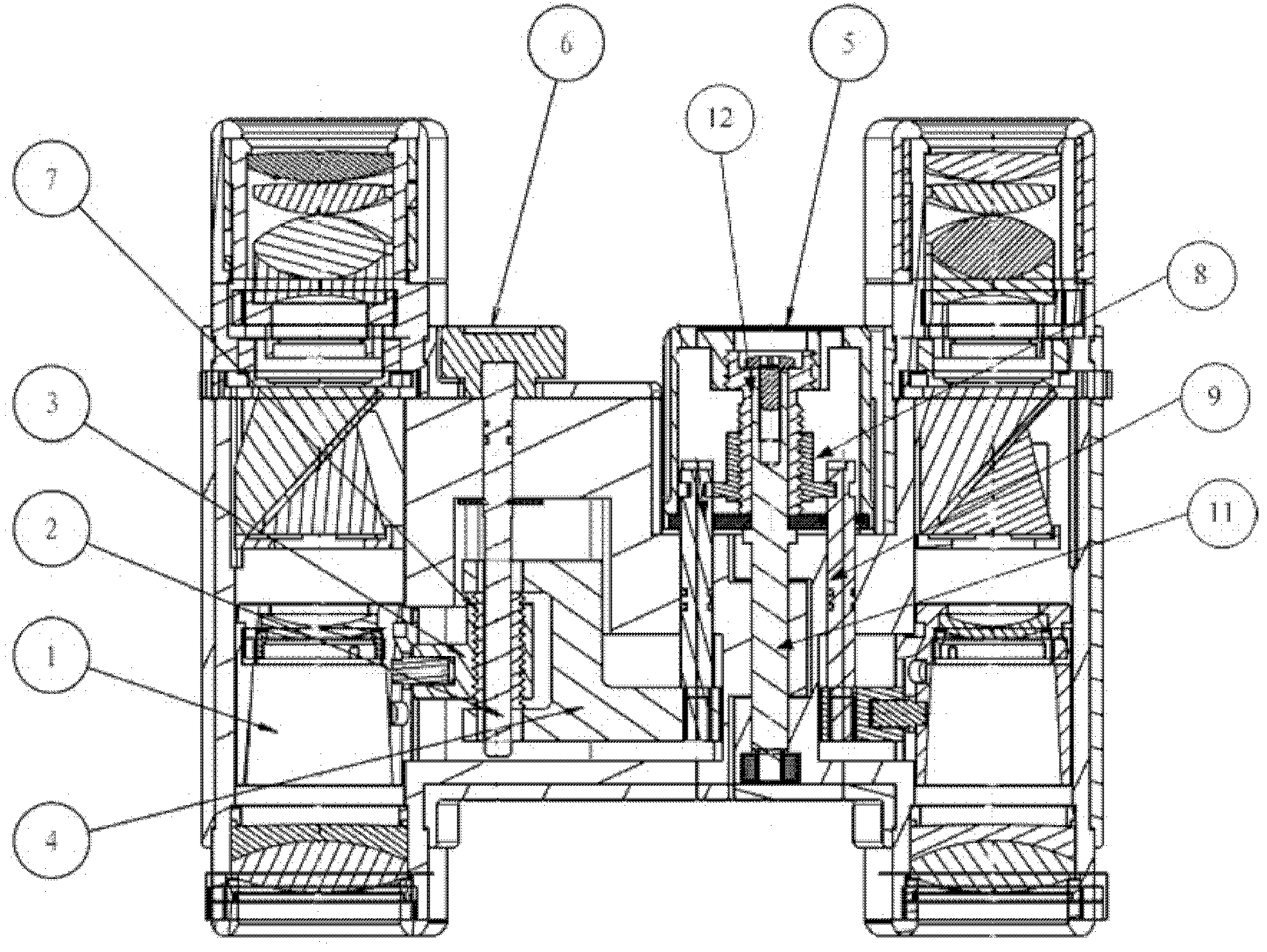
[0042] The following will be combined with figure 1 Or 2 clearly and completely describe the technical solutions of the various embodiments of the present invention, obviously, the described embodiments are only some of the embodiments of the present invention, not all of the embodiments. Based on the embodiments of the present invention, all other embodiments obtained by persons of ordinary skill in the art without making creative efforts belong to the protection scope of the present invention.

[0043] The invention provides a pair of binoculars. The binoculars include a first lens barrel and a second lens barrel. The axial directions of the first lens barrel and the second lens barrel are parallel to each other, and include a diopter adjustment assembly and a focal length an adjustment assembly, the diopter adjustment assembly is used to adjust the diopter of the first lens barrel based on the diopter of the second lens barrel, and the focal length adjustment assembly is us...


PUM


Abstract

The invention relates to the field of optical instruments, in particular to a binocular telescope and an adjustment method for the binocular telescope. The binocular telescope comprises a visual acuity adjustment component and a focal length adjustment component, wherein the visual acuity adjustment component is used for adjusting the visual acuity of a first lens barrel based on the visual acuity of a second lens barrel; and the focal length adjustment component is used for adjusting the focal length of the first lens barrel and the focal length of the second lens barrel at the same time. The adjustment method comprises the following steps of: taking the visual acuity of the second lens barrel as a reference, adjusting the visual acuity of the first lens barrel; and on the basis of keeping the visual acuity of the first lens barrel and the visual acuity of the second lens barrel unchangeable, adjusting the focal length of the first lens barrel and the focal length of the second lens barrel at the same time. The adjustment device provided by the invention has a simple structure and a small matching area with the main body of the binocular telescope, the production cost is greatly reduced, and the adjustment device is convenient to seal, and is simple and convenient to operate during adjustment.

Description

technical field [0001] The invention relates to the field of optical instruments, in particular to binoculars and an adjustment method thereof. Background technique [0002] In the prior art, the adjustment of the binoculars usually includes diopter adjustment and focus adjustment. The diopter adjustment is usually done by rotating the eyepiece or the objective lens, and then moving the eyepiece or the objective lens to complete the diopter adjustment. The focus is adjusted by turning the middle adjusting hand wheel , The diameter of the matching surface of the moving part of the eyepiece tube is 18mm-28mm, and the length is 10mm-28mm. The matching area is very large, and the adjustment is difficult and laborious. [0003] On the other hand, in the adjustment method of rotating the eyepiece, due to the large rotating area, in order to ensure the use effect of the binoculars, high processing accuracy is required, which increases the production cost of the binoculars; especial...

Claims


Application Information

Patent Timeline
Patent Type & Authority Patents(China)
IPC IPC(8): G02B23/00G02B23/18
Inventor 冯影
Owner 冯影
Learn More