
Enhanced reinforced plastic inspection well

A plastic inspection well and enhanced technology, which is applied in water conservancy projects, waterway systems, artificial islands, etc., can solve the problems of inconvenient cleaning by manual methods, insufficient strength of plastic castings, and not easy to clean at any time, so as to achieve settlement that is not easy to move and stable Strong and convenient connection, reducing the frequency of manual cleaning

Active Publication Date: 2013-08-28
四川亚塑新材料有限公司
View PDF5 Cites 0 Cited by
  • Summary
  • Abstract
  • Description
  • Claims
  • Application Information

AI Technical Summary

Problems solved by technology

[0006] During the use of inspection wells, falling objects often accumulate at the connection between the inner wall of the inspection well and the well base, which affects the use of the inspection well. At present, manual methods are usually used to remove them, but manual methods are inconvenient and difficult to achieve. to clean up
[0007] In addition, the current plastic pipe fitting type inspection well is manufactured by fixed molding. The branch pipe interface of the inspection well is also called the socket and the branch pipe is connected and fixed to complete the construction of the pipeline system. The current plastic pipe fitting type inspection well is relatively large in size. Due to the insufficient strength of the plastic casting, Often in the construction, when the branch pipe interface is connected with the branch pipe, the deformation of the branch pipe interface affects the construction quality, so it is necessary to strengthen the deformation resistance of the plastic pipe fitting type inspection well branch pipe interface

Method used


Image

  • Enhanced reinforced plastic inspection well
  • Enhanced reinforced plastic inspection well
  • Enhanced reinforced plastic inspection well

Examples


Embodiment 1

[0030] This embodiment is described by taking the straight-through plastic inspection well as an example.

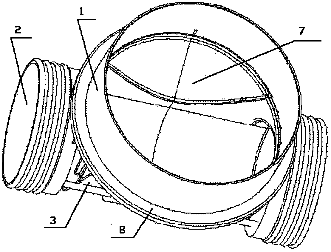
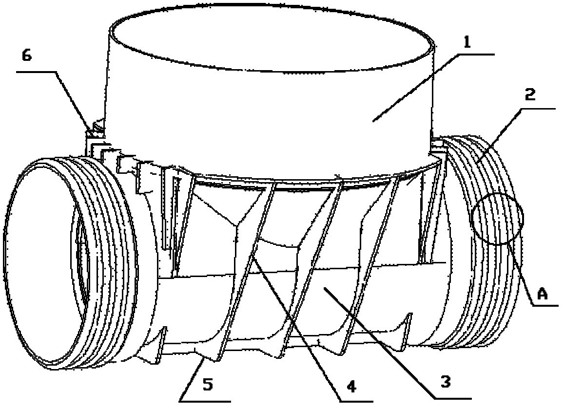
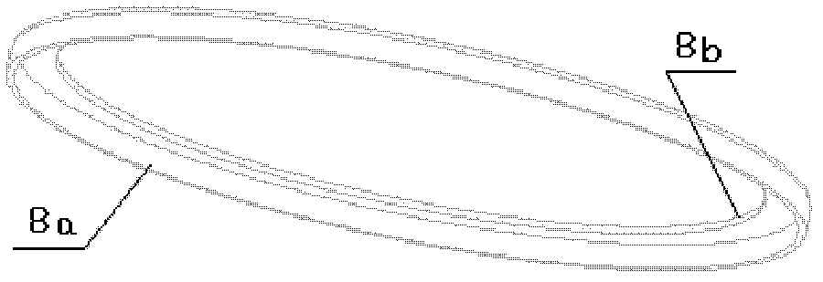
[0031] combine Figure 1 to Figure 5 ,as the picture shows, figure 1 It is a schematic diagram of the structure of the inspection well seat with retaining ring in the present invention; figure 2 It is a schematic diagram of the structure of the well seat of the inspection well without retaining ring in the present invention; image 3 It is a structural schematic diagram of the inspection well retaining ring of the present invention; Figure 4 yes figure 2 The enlarged schematic diagram of part A, that is, the schematic diagram of the corrugated reinforcing rib structure at the branch pipe interface, Figure 5 It is a schematic diagram of the mechanism at the bottom of the inspection well of the present invention.

[0032]Reinforced reinforced plastic inspection well, including well base 3, well head 1 and branch pipe interface 2, well head 1 is an inner socket con...

Embodiment 2

[0036] The other structures are the same as in Embodiment 1, except that there are further corrugated reinforcing ribs 2a arranged around the circumference of the branch pipe joint 2 on the outer surface of the branch pipe joint 2 . The stress area of ​​the corrugated rib 2a is 2.5 times that of the flat wall socket, and the force per unit area is relatively small, which greatly enhances the steel of the well seat ring and increases the strength of the load. The crest of the corrugated rib 2a is an arc, and the load is When the force is applied, the direction of the force is changed, so that the force can be decomposed and carried evenly; the present invention can further arrange reinforcing ribs in the axial direction of the branch pipe interface to increase the rigidity.

Embodiment 3

[0038] The other structures are the same as in Embodiment 1 or Embodiment 2, except that there is a groove transition structure 7 at the connection between the wellhead and the well seat on the inner wall of the inspection well. The groove transition structure 7 refers to the use of a concave slope at the connection between the inner wall of the cylindrical wellhead 1 of the inspection well and the inner wall of the well base 3, and the center of the wellhead 1 is lower than the edge of the wellhead 2, generally adopting an arc-shaped groove design; The arc-shaped groove with a certain inclination is conducive to the falling of falling objects. The arc-shaped groove has no edges, and the falling objects will not be blocked when falling, which greatly reduces the frequency of manual cleaning, reduces labor intensity, and saves maintenance costs.


PUM


Abstract

The invention discloses an enhanced reinforced plastic inspection well comprising a well base, a well head and a branch pipe interface, wherein the well head is in an internal bearing insert connection structure; reinforcing ribs are arranged at the bottom of the well base and on the outer wall of the side of the well base, the reinforcing ribs are arranged vertical to the surface of the outer wall along a well head columnar shaft, and the reinforcing ribs at the bottom are formed by extending the reinforcing ribs on the outer wall of the side of the well base; and one end of each reinforcingrib on the outer wall of the side of the well base is arranged along the circumference of the outer wall of the well head to form a step, and the step is provided with a dismountable load bearing retainer ring. The internal bearing insert connection structure in the invention can adapt to more extensive product sources and realize more stable, firmer and more convenient connection, the reinforcing ribs and the load bearing retainer ring improve strength of inspection well, installation settlement is uniform, the inspection well is difficult to move, connection bearing load transfer stress is uniform, a groove structure reduces cleaning frequency, maintenance cost is saved, corrugate reinforcing ribs of the branch pipe interface enhance stiffness of a well base ring, and load bearing stress strength is improved; and the dismountable load bearing retainer ring structure simplifies inspection well casting equipment, cost is reduced, and structure is further optimized.

Description

technical field [0001] The invention belongs to the field of pipeline fitting design and manufacture, in particular to the design and manufacture of inspection wells in large-scale pipeline systems, and in particular to the structural design of reinforced plastic inspection wells. Background technique [0002] Inspection wells in underground pipeline systems are also called pipeline wells and inspection wells. At present, large-scale underground pipelines are inspection wells such as sewers, industrial and mining sewage discharge pipelines, underground communications, and cable placement pipelines, especially for inspection wells in sewer pipelines. Most of them are built with bricks or cement under the ground in the pipeline passage. A well body reaches the ground, and then a well cover is built on it, and holes are opened on the side of the well body for pipeline connection; the existing problems are that the construction period is long, bushes and weeds are likely to be g...

Claims


Application Information

Patent Timeline
Patent Type & Authority Patents(China)
IPC IPC(8): E02D29/12E03F5/02
Inventor 陶功友
Owner 四川亚塑新材料有限公司
Learn More