
Field detection system for detecting partial discharge of cable and joint

A partial discharge and on-site detection technology, applied in the direction of testing dielectric strength, etc., can solve problems such as insulation defects, partial discharge, and insulation material aging, and achieve the effect of ensuring safe and reliable operation, removing on-site interference, and discovering timely

Inactive Publication Date: 2012-01-11
NANYANG POWER SUPPLY COMPANY OF STATE GRID HENAN ELECTRIC POWER
View PDF1 Cites 14 Cited by
  • Summary
  • Abstract
  • Description
  • Claims
  • Application Information

AI Technical Summary

Problems solved by technology

However, in the insulation structure of this kind of cable, there are often air gaps and harmful impurities due to the difficulty of processing technology or the impurity of raw materials, or there is a gap between the insulation and the semi-conductive shielding layer or the semi-conductor to the insulation due to process reasons. The layer protrudes, and partial discharges are easily generated at the tips of these air gaps and impurities. At the same time, various insulation defects may also occur during the installation and operation of power cables to cause partial discharges.
Due to the poor discharge resistance of extruded insulating materials such as XLPE, under the long-term action of partial discharge, the insulating materials will continue to age and eventually lead to insulation breakdown, resulting in major accidents

Method used


Image

  • Field detection system for detecting partial discharge of cable and joint
  • Field detection system for detecting partial discharge of cable and joint
  • Field detection system for detecting partial discharge of cable and joint

Examples


Embodiment Construction

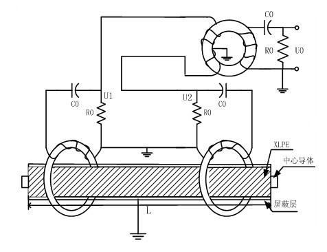
[0013] like figure 1 , figure 2 , image 3 As shown, the on-site detection system for cable and joint partial discharge of the present invention, on the basis of a large number of experiments, constantly sums up experience, implements scientifically, design scientifically, and analyzes strictly to obtain this system, which includes hardware devices and software systems. The hardware device includes a broadband differential current sensor, a signal conditioning module, and a data acquisition card. The broadband differential current sensor is composed of a magnetic core, a Rogowski coil, a filtering and sampling unit and an electromagnetic shielding box. The signal conditioning module includes a trigger signal circuit and an amplifier. The software system is labVIEW software of virtual instrument technology.

[0014] Below in conjunction with embodiment for further explanation.

[0015] A wide-band differential current sensor is developed on the basis of a wide-band curren...


PUM


Abstract

The invention discloses a field detection system for detecting the partial discharge of a cable and a joint, which comprises a hardware device and a software system. The hardware device comprises a broadband differential current sensor, a signal conditioning module and a data acquisition card. The broadband differential current sensor consists of a magnetic core, a Rogowski coil, a filtering and sampling unit and an electromagnetic shielding box. The signal conditioning module comprises a trigger signal circuit and an amplifier. The software system is labVIEW software in a virtual instrument technology. Signals are acquired from both ends of the cable and the joint by the broadband differential current sensor; after passing through the sensor, the signals enter the signal conditioning modules to be conditioned and amplified and then are sent into the data acquisition card so that analog signals are converted into digital signals; and the digital signals are sent into an internal memory of a computer to be subjected to anti-interference treatment in real time by a PCI (Peripheral Component Interconnect) bus; data subjected to interference removal is written into a database; and after repeated acquisition, the data is extracted from the database to carry out spectra analysis and data report so as to know partial discharge information of the cable and the joint and judge whether the partial discharge hidden danger exists or not.

Description

[0001] technical field [0002] The invention belongs to the technical field of power equipment maintenance, and in particular relates to an on-site partial discharge detection system for cables and joints. Background technique [0003] In the past ten years, extruded power cables, especially XLPE power cables, have been widely used in urban power grids due to their good insulation performance, easy manufacturing, convenient installation, safe and reliable power supply, and benefits for urban and factory layouts. However, in the insulation structure of this kind of cable, there are often air gaps and harmful impurities due to the difficulty of processing technology or the impurity of raw materials, or there is a gap between the insulation and the semi-conductive shielding layer or the semi-conductor to the insulation due to process reasons. Layers protrude, and partial discharges are easily generated at these air gaps and impurity tips. At the same time, various insulation d...

Claims


Application Information

Patent Timeline
Patent Type & Authority Applications(China)
IPC IPC(8): G01R31/12
Inventor 姚楠
Owner NANYANG POWER SUPPLY COMPANY OF STATE GRID HENAN ELECTRIC POWER
Learn More