
Cooling arrangement for internal combustion engines

一种冷却设备、发动机的技术,应用在发动机的冷却、机械设备、发动机元件等方向,能够解决结构空间限制等问题,达到简单内部构造、小结构空间、体积小的效果

Inactive Publication Date: 2012-01-11
FORD GLOBAL TECH LLC
View PDF7 Cites 13 Cited by
  • Summary
  • Abstract
  • Description
  • Claims
  • Application Information

AI Technical Summary

Problems solved by technology

[0012] Due to today's stringent requirements on the spatial structure of the engine which usually accommodates the cooling equipment of motor vehicles, e.g. providing pedestrian protection measures, accommodating complex drive trains and low weight, the available construction space is greatly limited

Method used


Image

  • Cooling arrangement for internal combustion engines
  • Cooling arrangement for internal combustion engines
  • Cooling arrangement for internal combustion engines

Examples


Embodiment Construction

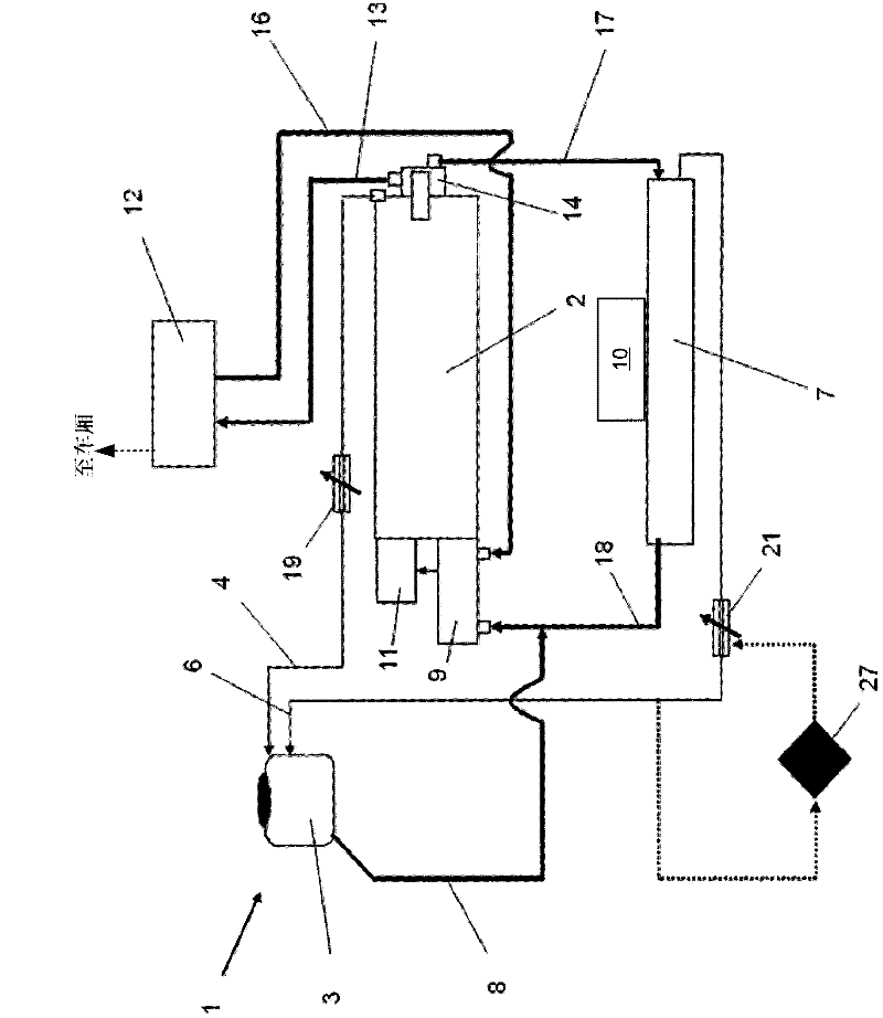
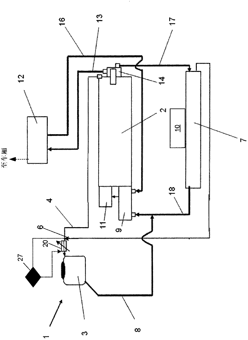
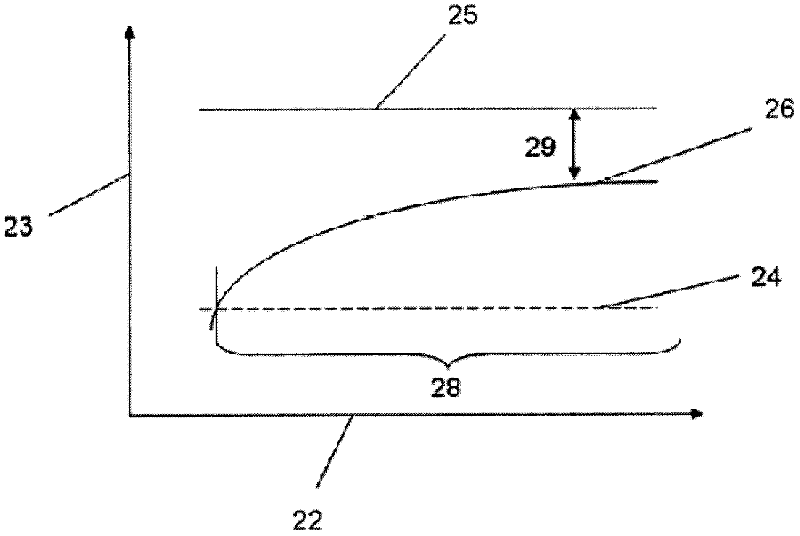
[0051] In order to ensure a satisfactory ventilation of the cooling circuit, the permissible operating range of the cooling device is mainly determined by various factors described below. The separation of the gas components contained in the coolant from the cooling circuit generally depends on the flow rate of the coolant in the cooling circuit. Therefore, on the one hand, a minimum flow rate of the coolant inside the ventilation duct is necessary in order to ensure a satisfactory ventilation of the entire cooling circuit, but, on the other hand, a flow rate that is too high leads to foaming of the coolant and thus to increased air Mixing into the coolant, and moreover, leads to an excessive reduction of the coolant level in the balance tank. Since the coolant pump that circulates the coolant in the cooling circuit is usually driven via the internal combustion engine or the crankshaft of the internal combustion engine, with a predetermined fixed line cross-section in the cool...


PUM


Abstract

A cooling arrangement for an internal combustion engine is described, with a coolant balancing tank which is capable of being filled with coolant and the inlet side of which is connected via a first venting line to an internal combustion engine and / or via a second venting line to a cooler for cooling the coolant, and the outlet side of which is connected via a coolant return line to the inlet side of a pumping device for pumping the coolant through the internal combustion engine. The cooling arrangement has, furthermore, a flow control unit for variably limiting the coolant volume flow in the venting line.

Description

[0001] related application [0002] This application claims priority from German Patent Application No. 102010017766.0 filed on July 6, 2010, the entire content of which is hereby incorporated by reference. technical field [0003] The invention relates to a cooling arrangement for an internal combustion engine, in particular for an internal combustion engine of a motor vehicle. Background technique [0004] A cooling device for an internal combustion engine provides for example the intrinsic function of cooling the internal combustion engine and other components of a motor vehicle and, where appropriate, utilizes heated coolant as a heat source for eg a heating device of an air conditioning system of a motor vehicle. It is also important for these cooling devices that the air contained in the cooling circuit of the cooling device is regularly removed from the circuit. [0005] Therefore, in general, a balance tank is provided in the cooling equipment. In particular, this ...

Claims


Application Information

Patent Timeline
Patent Type & Authority Applications(China)
IPC IPC(8): F01P11/02
CPCF01P11/0285F01P2060/06F01P7/165F01P11/029
Inventor B·布林克曼H·G·奎科斯J·梅林H·查克K·格勒克P·冈瑟
Owner FORD GLOBAL TECH LLC
Learn More