
Circuit and method for generating clock pulse data reply signal phase locked index

A technology of clock pulse and signal phase, applied in the direction of electrical components, automatic power control, etc., can solve the problem of not being equal

Active Publication Date: 2013-04-24
EEVER TECH INC
View PDF4 Cites 0 Cited by
  • Summary
  • Abstract
  • Description
  • Claims
  • Application Information

AI Technical Summary

Problems solved by technology

Therefore, the above method of generating clock pulse data to restore the signal phase lock indicator is not a good choice for users.

Method used


Image

  • Circuit and method for generating clock pulse data reply signal phase locked index
  • Circuit and method for generating clock pulse data reply signal phase locked index
  • Circuit and method for generating clock pulse data reply signal phase locked index

Examples


Embodiment Construction

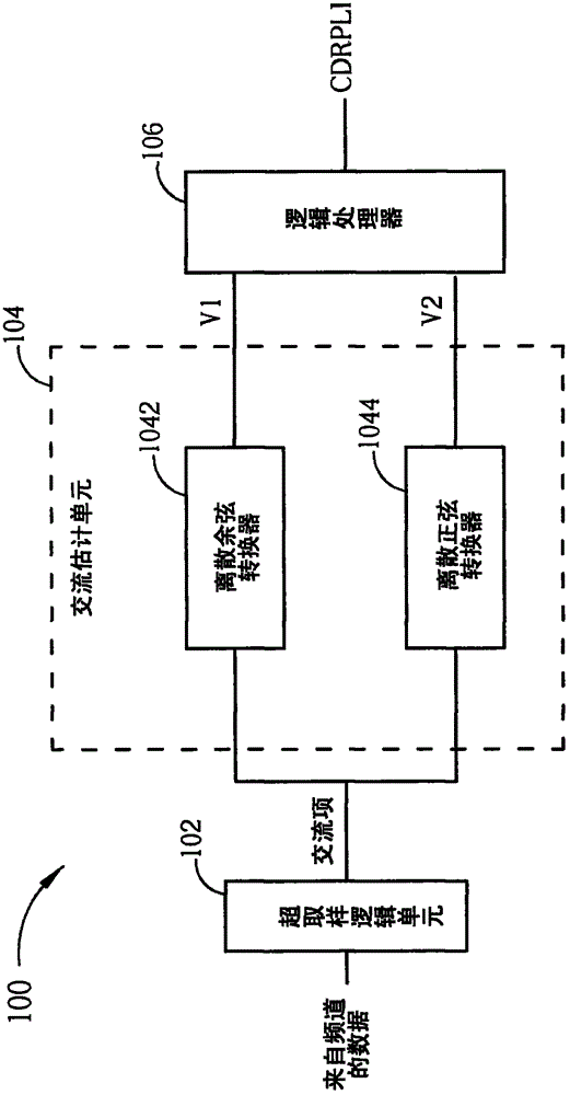
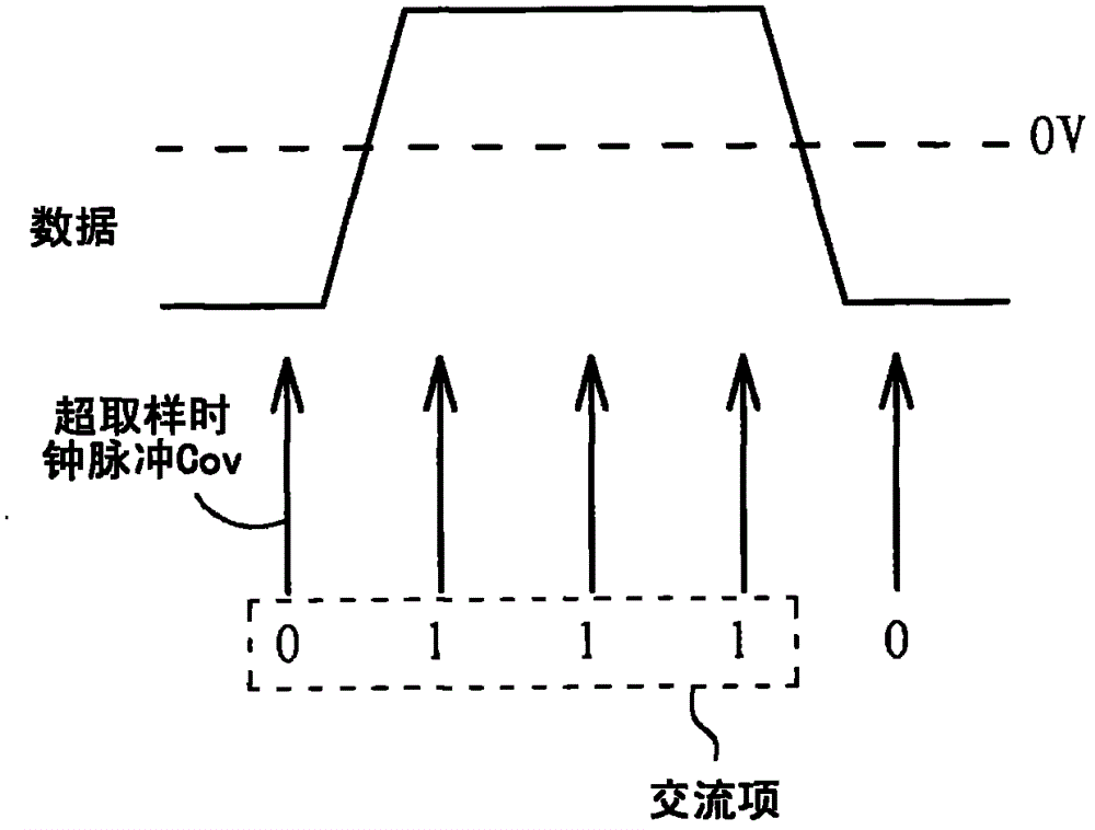
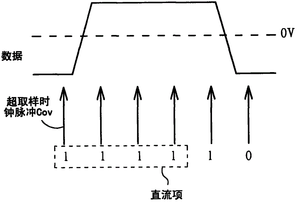
[0018] Please refer to figure 1 , figure 1 A schematic diagram of a circuit 100 for generating a phase lock indicator of a clock pulse data recovery signal is illustrated for an embodiment of the present invention. The circuit 100 includes an oversampling logic unit 102 , an AC estimation unit 104 and a logic processor 106 . The over-sampling logic unit 102 is used to perform an over-sampling operation on data from a channel according to an over-sampling clock Cov to generate a plurality of AC terms, and according to an output clock Co, A plurality of AC terms associated with the output clock Co is output from the plurality of AC terms. In addition, the frequency of the oversampling clock Cov must be greater than twice the frequency of the data. In this embodiment, the oversampling clock Cov is 10 GHz and the data frequency is 2.5 GHz, but the present invention is not limited to the oversampling clock Cov being 10 GHz and the data frequency being 2.5 GHz.

[0019] Please r...


PUM


Abstract

The present invention discloses a circuit and a method for generating a clock pulse data reply signal phase locked index. The circuit includes an oversampling logic unit, an alternating current estimator, and a logic processor. The oversampling logic unit generates a plurality of alternating current terms according to an oversampling clock pulse, and outputs a plurality of alternating current terms corresponding to an output clock pulse from the plurality of alternating current terms according to the output clock pulse. The alternating current estimator executes a discrete cosine transform and a discrete sine transform on a plurality of alternating current terms output from the oversampling logic unit within a first predetermined time to generate a first value and a second value respectively. The logic processor compares a number of first values and a number of second values within a second predetermined time, and generates a clock pulse data reply signal phase locked index according to a comparing result.

Description

technical field [0001] The present invention relates to a circuit and method for generating clock pulse data reply signal phase lock indicator, especially a kind of multiple exchange items generated after performing oversampling on data of a channel to generate clock pulse data reply Circuit and method for signal phase locking indicator. Background technique [0002] In the prior art, the phase lock loop lock indicator can be used to generate the lock indicator of the clock pulse data recovery device based on the phase locked loop; the known bit pattern can be transmitted and checked The error rate of the returned bit is used to generate the phase lock index of the clock pulse data recovery signal; the known reference clock pulse can be used to compare the reference clock pulse and the clock pulse of the clock pulse data recovery device to generate the clock pulse data recovery signal phase Lock indicator. [0003] If the clock data recovery device is not based on the phas...

Claims


Application Information

Patent Timeline
Patent Type & Authority Patents(China)
IPC IPC(8): H03L7/06
Inventor 许惠强赵轩庆郭国铨陈铭楷
Owner EEVER TECH INC
Learn More