
Method for detecting smoothness of high-speed railway track

A technology for high-speed railways and detection devices, applied in the field of optical measurement, can solve the problems of limited measurement accuracy, long-wave irregularity, and measurement accuracy of irregularity, and achieve the effects of improving detection efficiency, high-stability measurement, and suppressing errors

Inactive Publication Date: 2013-08-14
CHANGCHUN UNIV OF SCI & TECH
View PDF5 Cites 0 Cited by
  • Summary
  • Abstract
  • Description
  • Claims
  • Application Information

AI Technical Summary

Problems solved by technology

At present, the detection methods of the track are mainly divided into the inertial reference method and the chord measurement method. The inertial reference method is generally used for large-scale rail inspection vehicles. The position or displacement is directly obtained by quadratic integration of the acceleration signal of the train, and the inertial reference is obtained. The disadvantage is that the measurement results are affected by the driving speed, and can only be used to detect the completed road sections. The manufacturing and use costs are high, and it is not convenient for daily line inspection and maintenance.
Portable rail inspection cars mostly use the chord measurement method, which calculates the long-wave irregularity by measuring the height of the short chord (CN200971459). Due to the small size and the large size, there are problems such as error amplification, and the chord measurement method has poor convergence of the transfer function, and the measured value cannot be completely measured. It truly reflects the state of the track, and can only be converted to the measured value at a wavelength of 40 meters through inverse filtering
In order to improve the measurement accuracy of long-wave irregularities, Dalian Latt Laser Co., Ltd. uses the laser collimation method for long-string measurement (CN201575794U). The disadvantage is that it cannot overcome the random jitter of the laser spot caused by atmospheric turbulence, the interpretation error of the center of the spot and vibration, etc. will limit the further improvement of measurement accuracy.

Method used


Image

  • Method for detecting smoothness of high-speed railway track
  • Method for detecting smoothness of high-speed railway track
  • Method for detecting smoothness of high-speed railway track

Examples


Embodiment Construction

[0024] The present invention will be described in further detail below in conjunction with accompanying drawing

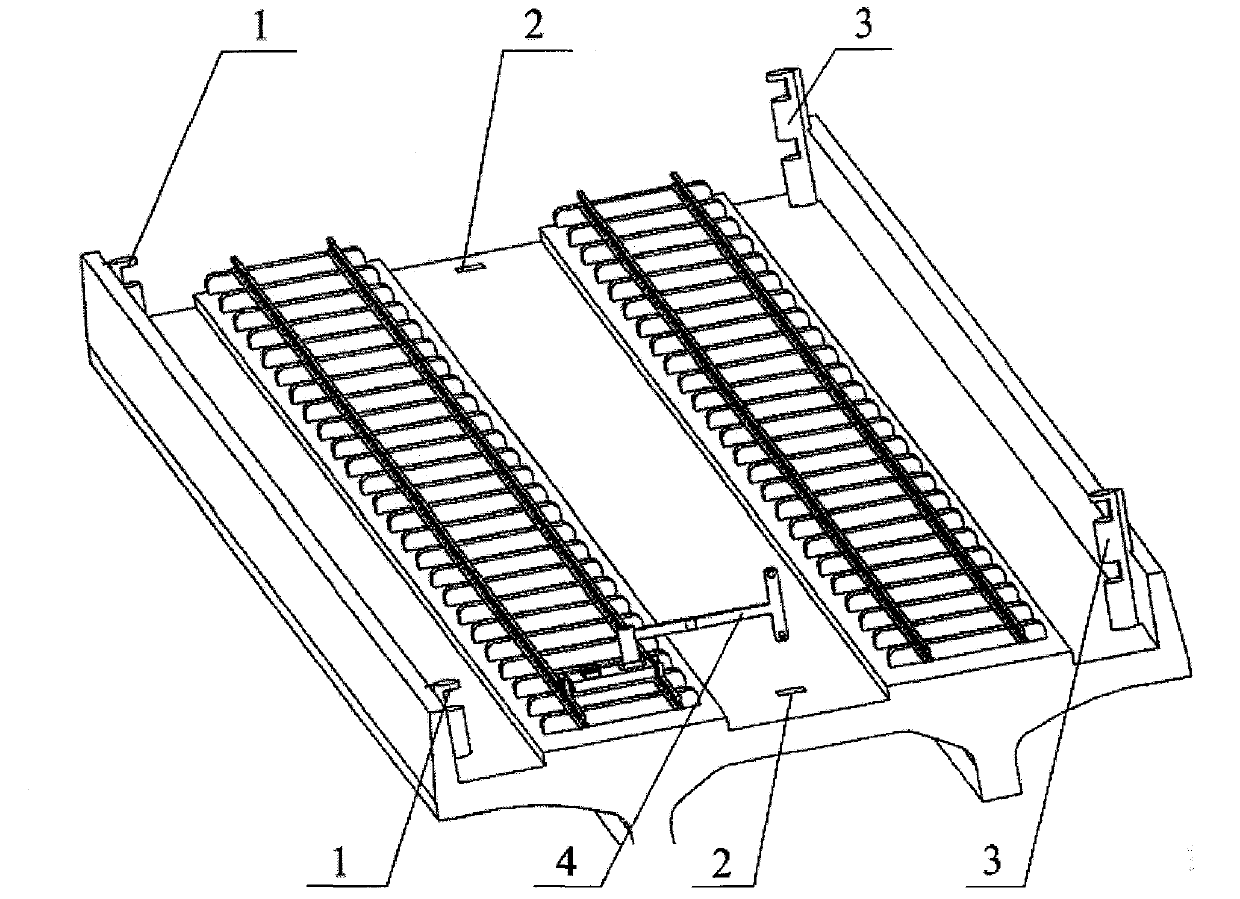
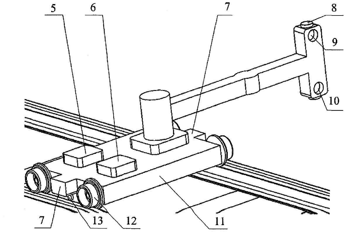
[0025] Such as figure 1 and figure 2 , a kind of detection method of track smoothness of high-speed railway involved in the present invention, mainly is made up of measuring trolley (4), optical reference station (2) and reference mark post, and wherein measuring trolley (4) mainly comprises lateral phase-locked measuring head ( 10), vertical phase-locked measuring head (9), automatic leveling plummet (8), gauge laser measuring device (13), horizontal laser distance measuring device (7), trolley body (11), trolley wheel rail (12), a power supply and drive module (5) and a data processing and storage module (6), and the benchmark includes a benchmark A type (1) and a benchmark B type (3).

[0026] The reference mark A type (1) has a spherical prism, the reference mark B type (3) has two vertically separated spherical prisms, and the spherical prism is used as a r...


PUM


Abstract

The invention belongs to the field of optical measurement, and relates to an apparatus for detecting smoothness of a high-speed railway track. According to the detection apparatus, a measurement trolley (4), an optical reference station (2) and a reference marker post are mainly adopted in the method; traditional detection principles of an inertial reference method and a chord measurement method are broken; and the distance difference is measured by adopting a double-frequency laser ratio contrapuntal phase method, the smoothness of the track is measured by measuring long resolution capability, and spatial high-precision measurement is further finished by using the accuracy of time. The invention provides the new high-precision track smoothness detection method, so that technical guarantee is provided for realizing safety and comfortableness of higher speed operation in high-speed railways; and the method can be widely applied in the field of precise measurement such as linearity measurement of high-precision ultra long tracks, deformation monitoring of large dams, maintenance and detection of subway tracks and the like.

Description

technical field [0001] The invention belongs to the technical field of optical measurement, and relates to a detection device for smoothness of high-speed railway tracks. Background technique [0002] With the rapid development of my country's high-speed railway system, the speed of train operation is getting faster and faster, and the requirements for the smoothness of high-speed railway tracks are getting higher and higher. At present, the detection methods of the track are mainly divided into the inertial reference method and the chord measurement method. The inertial reference method is generally used for large-scale rail inspection vehicles. The position or displacement is directly obtained by quadratic integration of the acceleration signal of the train, and the inertial reference is obtained. The disadvantage is that the measurement results are affected by the driving speed, and can only be used to detect completed road sections. The manufacturing and use costs are hi...

Claims


Application Information

Patent Timeline
Patent Type & Authority Patents(China)
IPC IPC(8): G01C9/00E01B35/00
Inventor 贺文俊郑阳王加科张磊郑建平
Owner CHANGCHUN UNIV OF SCI & TECH
Learn More