Plunger rod type steel ladle lifting mechanism

A lifting mechanism and plug-rod type technology, applied in the direction of mechanical equipment, engine components, valve details, etc., can solve the problems of increased gap between the guide groove and the slide bar, difficulty in lifting the slide bar, and failure to open and close the gate normally. To achieve the effect of smooth lifting operation

Active Publication Date: 2012-11-21
SUFA HENGDIAN MACHINERY CNNC
View PDF0 Cites 1 Cited by
  • Summary
  • Abstract
  • Description
  • Claims
  • Application Information

AI Technical Summary

Problems solved by technology

Both the existing guide groove and the slide rod adopt a square structure. After long-term use, the gap between the guide groove and the slide rod will increase, which will make it difficult to lift the slide rod. Normal opening and closing gate

Method used


Image

  • Plunger rod type steel ladle lifting mechanism
  • Plunger rod type steel ladle lifting mechanism

Examples


Embodiment Construction

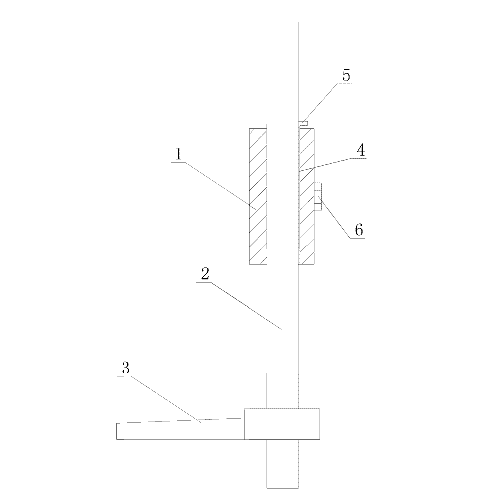
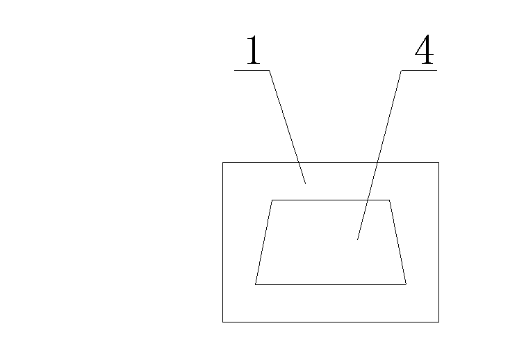
[0011] like figure 1 and figure 2 As shown, the plug-rod type ladle lifting mechanism includes a guide device 1, a slide rod 2 arranged on the guide device 1, and a pressing rod 3 arranged on the slide rod 2. The guide groove 4, the slide bar 2 adopts a trapezoidal structure, and the guide groove 4 adopts a trapezoidal structure corresponding to the slide bar 2. A pad iron 5 corresponding to the slide bar 2 is arranged in the guide groove 4 . The guide device 1 is provided with fastening bolts 6 corresponding to the slide bars 2 . The lifting operation of the slide bar is guaranteed to be smooth, and the center of the plug rod on the slide bar is easily aligned with the center of the nozzle.


PUM


Abstract

The invention provides a plunger rod type steel ladle lifting mechanism, which comprises a guiding device, a slide bar arranged on the guiding device, and a press bar arranged on the slide bar. A guiding groove which corresponds to the slide bar is arranged in the guiding device; the slide bar is in a trapezoidal structure; and the guiding groove is in a trapezoidal structure which corresponds tothe slide bar. With the adoption of the plunger rod type steel ladle lifting mechanism, the smooth operation of lifting of the slide bar can be ensured and the center of a plunger on the slide bar iseasy to align with the center of a water gap.

Description

technical field [0001] The invention relates to a plug rod type ladle lifting mechanism. Background technique [0002] The existing ladle lifting mechanism includes a guide device, a slide bar arranged on the guide device, and a pressing bar arranged on the slide bar. The guide device is provided with a guide groove corresponding to the slide bar. By applying force to the press bar, the slide bar Slide up and down in the guide groove, and the plug rod on the slide rod corresponds to the center of the nozzle to achieve the purpose of opening and closing the gate. Both the existing guide groove and the slide rod adopt a square structure. After long-term use, the gap between the guide groove and the slide rod will increase, which will cause difficulty in the lifting operation of the slide rod. Open and close the gate normally. Contents of the invention [0003] The technical problem to be solved by the present invention is to provide a stopper rod type ladle lifting mechani...

Claims


Application Information

Patent Timeline
Patent Type & Authority Patents(China)
IPC IPC(8): F16K31/44
Inventor 魏代钢丁晓晶
Owner SUFA HENGDIAN MACHINERY CNNC
Why Eureka
Try Eureka