Mold for die casting machine of lead-acid storage battery plate grid

A technology for lead-acid batteries and die-casting machines, which is applied in the field of molds for lead-acid battery grid die-casting machines. Effects of grid quality problems, quality assurance, and yield improvement

Inactive Publication Date: 2013-07-24
JIANGSU SANHUAN IND HLDG CO LTD
View PDF6 Cites 0 Cited by
  • Summary
  • Abstract
  • Description
  • Claims
  • Application Information

AI Technical Summary

Problems solved by technology

[0005] Since the ejection mechanism configured on the existing mold is exposed, and when the ejector pin is ejected from the grid, it not only bears the axial ejection force, but also bears the radial force. Therefore, the prior art exists: 1. The ejector pin 109 and the ejector pin The matching accuracy of the hole decreases rapidly with use, which affects the airtightness of the ejector pin hole; 2. The ejector pin hole is easily blocked by waste lead liquid pollution, and the return spring is easily contaminated with waste lead liquid, which affects the normal reset of the ejector mechanism; 3. The two rows of ejector pins 109 opposite to the two ends of the grid easily deform or fail to eject the soft grid top just after forming, resulting in scrapping of the grid

Method used


Image

  • Mold for die casting machine of lead-acid storage battery plate grid
  • Mold for die casting machine of lead-acid storage battery plate grid
  • Mold for die casting machine of lead-acid storage battery plate grid

Examples


Embodiment Construction

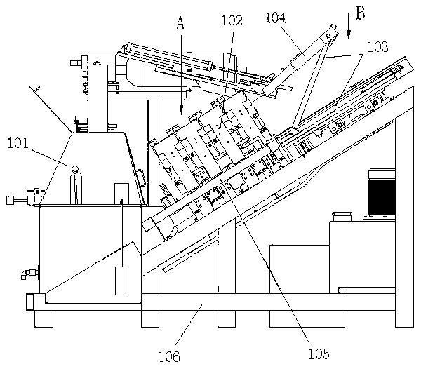
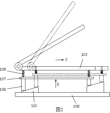
[0027] The structure of the mold of the present invention is described in detail below according to the accompanying drawings, wherein the end where the injection port of the mold 104 is set is the rear end of the mold, the opposite end is the front end, and the two sides between the rear end and the front end of the mold are sides. Set the up and down directions according to the use state of the mold, that is, the base plate is located below the fixed plate.

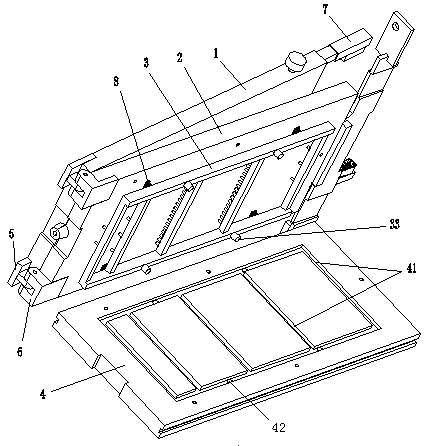
[0028] Such as image 3 , Figure 4 As shown, the mold of the present invention includes a movable mold 1 and a fixed mold; the fixed mold includes a fixed template 2, a base plate 4 and an ejector device 3, and the base plate 4 is covered on the lower surface of the fixed template 2, and the ejector device 3 is buckled on the In the accommodating cavity provided on the upper surface of the bottom plate 4. The bottom plate 4 and the fixed formwork 2 are fixed by screws, see Figure 7 , the hole 22 on the lower surfac...


PUM


Abstract

The invention discloses a mold for a die casting machine of a lead-acid storage battery plate grid. The mold comprises a moving die and a fixed die, wherein the fixed die comprises a fixed die plate, a bottom plate and an ejecting device; the bottom plate is arranged on the lower surface of the fixed die plate in a covering manner; the ejecting device is fastened in a containing cavity arranged on the lower surface of the fixed die plate or the upper surface of the bottom plate; a plurality of rows of ejecting needles are fixed on the ejecting device, and are respectively inserted in ejectingneedle holes on the lower surface of the fixed die plate in a one-to-one manner; and a pushing hole is arranged on the lower surface of the bottom plate, and a pushing rod on an outer ejecting mechanism penetrates through the pushing hole and then pushes the ejecting device to move upwards, so as to lead the ejecting needles to be ejected out upwards. According to the mold, the work finished by aset of outer ejecting mechanism is changed to be finished by two sets of inner and outer ejecting mechanisms together, the completeness of the mold is guaranteed, the pollution of the ejecting needleholes, the ejecting needles and a return spring by waste lead liquid is avoided, the stressing of the ejecting needles is improved, the working reliability of the mold is guaranteed, and the condition for improving the yield of finished plate grids is created.

Description

technical field [0001] The invention relates to a die for a lead-acid storage battery grid die-casting machine. Background technique [0002] The structure of the lead-acid battery grid die-casting machine is as follows: figure 1 As shown, it includes a lead pot 101, a mold shifting and locking mechanism 102, a mold 103, and a mold opening mechanism 104. When performing grid production, the mold shifting cylinder 105 first drags the mold 103 into the die-casting station A where the mold shifting and clamping mechanism 102 is located to perform grid die-casting. After the grid in the mold 103 is formed, the mold 103 is pushed to the The grid take-out station B on the die-casting machine takes out the grid. [0003] Since the grid to be taken out is embedded in the forming groove on the fixed template of the mold, in order to facilitate the taking out of the grid, it is necessary to equip the mold 103 with a special ejection mechanism. After the mold 103 moves to the grid ta...

Claims


Application Information

Patent Timeline
Patent Type & Authority Patents(China)
IPC IPC(8): B22D25/04B22D17/22
Inventor 汪群华朱晨
Owner JIANGSU SANHUAN IND HLDG CO LTD
Why Eureka
Try Eureka