
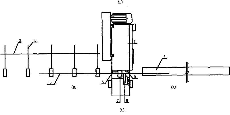
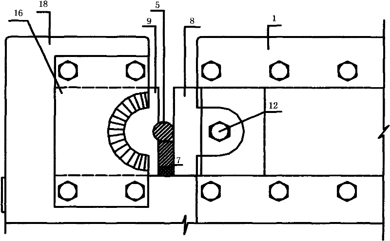
Straight end steel bar cutting machine

A steel bar cutting machine, cutting machine technology, applied in the field of steel bar cutting machine, can solve the problems of high cost, inability to use straight thread threading, hindering the development of steel bar connection technology, etc.

Active Publication Date: 2011-12-21
北京城建二建设工程有限公司
View PDF6 Cites 7 Cited by
  • Summary
  • Abstract
  • Description
  • Claims
  • Application Information

AI Technical Summary

Problems solved by technology

[0002] In the straight thread connection of steel bars, because the end of the steel bar cut by the ordinary steel bar cutter has a slope and a horseshoe shape, it cannot be used for straight thread threading.
Rebar ends cut with a toothless saw are ideal, but drawbacks such as high cost and low efficacy have hindered the development of rebar joining processes for many years

Method used


Image

  • Straight end steel bar cutting machine
  • Straight end steel bar cutting machine
  • Straight end steel bar cutting machine

Examples


Embodiment Construction

[0024] 1. First, adjust and position the steel plate gasket in the middle of the top pressing block according to the diameter of the steel bar to be cut. (The steel plate gasket is designed to be E-shaped, and an arc-shaped gap is set between the block and the head steel plate to facilitate the removal of the gasket) so that the steel bar and the fixed blade form an included angle of 90 degrees.

[0025] 2. Adjust the height adjustment pad so that the steel bars to be cut are placed at the arc of the blade of the arc-shaped incision cutting machine. If 2 or 3 pieces are cut each time, 2 or 3 arc-shaped incision steel bar cutting machines can be used. The blade makes 2 and 3 steel bars horizontally arranged and integrated into one, and then enters the arc-shaped incision to cut off.

[0026] 3. The continuous cutting operation method can be used for single cutting, and the foot-operated cutting method should be used for cutting 2 or 3 roots at a time.

[0027] 4. Before the st...


PUM


Abstract

A straight end steel bar cutting machine is characterized in that the machine not only has the common functions of ordinary steel bar cutting machines, but also has a positioning top pressure block on the other side of its incision, which can automatically cut off the steel bar at the moment before cutting. Hold the steel bar to be cut and form a 90-degree angle with the blade. The ends of the steel bars cut by this machine are straight and have no slope and horseshoe shape. Between the bottom blade in the cutout and the positioning top pressure block, a height adjustment pad is set. The A side of the machine is equipped with a fixed-length channel steel, and the B side is equipped with a roller-type horse stool rack. There are two main functions of this machine: it can not only use the arc-shaped incision steel bar cutting machine blade, and the cut steel bar can be directly used for straight thread threading; but also can use the ordinary steel bar cutting machine blade for ordinary cutting. There are two ways of operation: continuous cutting and pedal cutting. It has the advantages of high efficiency and low consumption, and solves the problems in the straight thread connection process for many years.

Description

(1) Technical field [0001] The invention relates to a steel bar cutting machine, in particular to a straight end steel bar cutting machine. (2) Background technology [0002] In the straight thread connection of steel bars, because the end of the steel bar cut by the ordinary steel bar cutter has a bevel and a horseshoe shape, it cannot be used for straight thread threading. Rebar ends cut with a toothless saw are ideal, but drawbacks such as high cost and low efficacy have hindered the development of the rebar joining process for many years. (3) Contents of the invention [0003] The purpose of the present invention is to add a positioning pressing function on the basis of the common steel bar cutting machine, that is: positioning pressing block. (Combined with arc-shaped incision steel bar cutting machine blade) so that the cut steel bar end can be directly used for straight thread threading, and fully meet the quality requirements. In order to achieve the purpose of h...

Claims


Application Information

Patent Timeline
Patent Type & Authority Applications(China)
IPC IPC(8): B21F11/00
Inventor 梁超梁绍平耿士红方玉新
Owner 北京城建二建设工程有限公司
Learn More