
A braking resistor protection method and device for the main circuit of an electric train

A technology for braking resistors and protection equipment, applied in the field of power electronics, can solve problems such as increased cost, uneven temperature distribution of braking resistors, inaccurate braking resistor protection, etc., and achieves the effect of avoiding burnout

Inactive Publication Date: 2011-12-14
SHENZHEN INVT TRANSPORTATION TECH CO LTD
View PDF4 Cites 10 Cited by
  • Summary
  • Abstract
  • Description
  • Claims
  • Application Information

AI Technical Summary

Problems solved by technology

[0004] 1) The internal temperature distribution of the braking resistor is not uniform, it is difficult to ensure that the temperature measured by the temperature sensor is the temperature of the highest point of the braking resistor, and the braking resistor protection is not accurate enough;
[0005] 2), the use of temperature sensors will add additional failure points, which will reduce the overall reliability of the system;
[0006] 3) The operating environment of electric trains is relatively harsh, and the braking resistor works in a high-temperature and high-vibration environment all the year round, so the requirements for the selection of temperature sensors are relatively high, which increases the cost

Method used


Image

  • A braking resistor protection method and device for the main circuit of an electric train
  • A braking resistor protection method and device for the main circuit of an electric train
  • A braking resistor protection method and device for the main circuit of an electric train

Examples


Embodiment Construction

[0027] The following will clearly and completely describe the technical solutions in the embodiments of the present invention with reference to the accompanying drawings in the embodiments of the present invention. Obviously, the described embodiments are only some, not all, embodiments of the present invention. Based on the embodiments of the present invention, all other embodiments obtained by persons of ordinary skill in the art without creative efforts fall within the protection scope of the present invention.

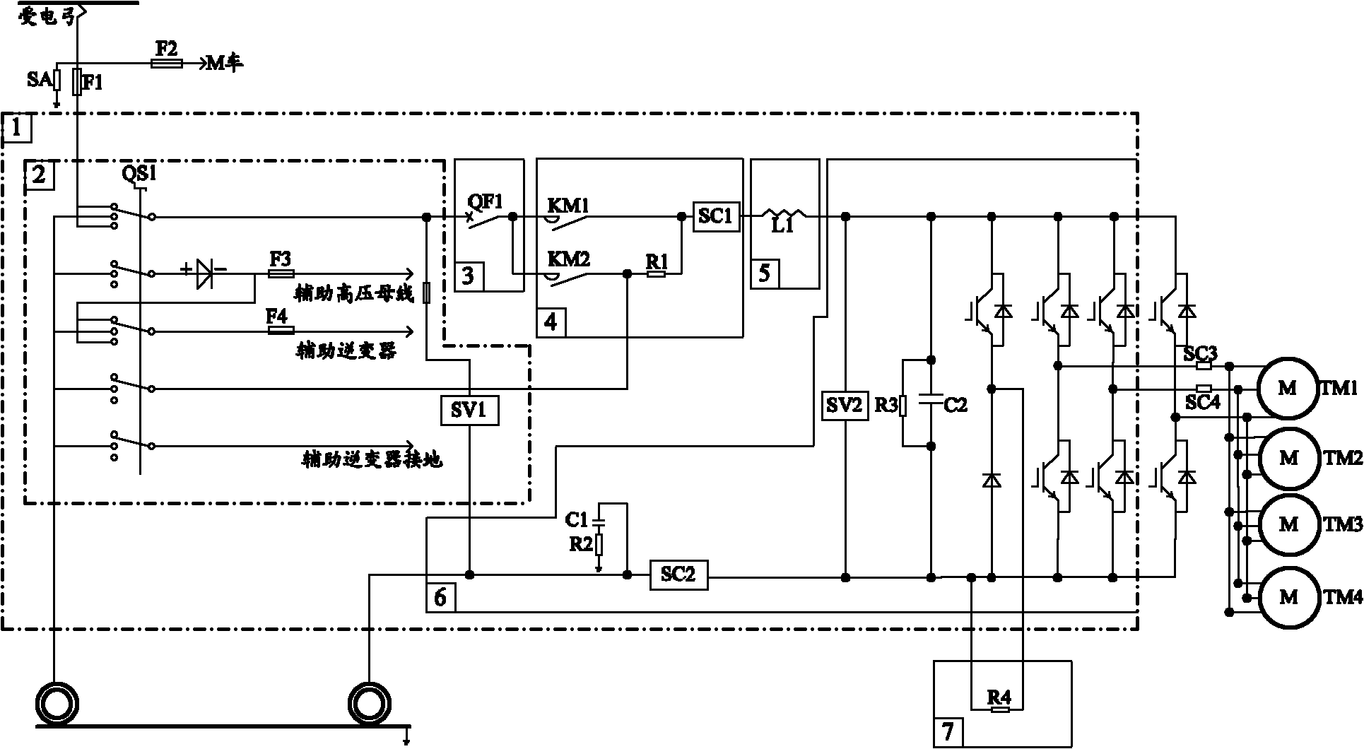
[0028] In order to better understand the braking resistor protection method and equipment for the main circuit of the electric train provided by the embodiments of the present invention, the application scenarios involved in the embodiments of the present invention will be described below. see figure 1 , figure 1 It is a schematic diagram of the main circuit of an existing electric train. Such as figure 1 As shown, the existing electric train main circuit is mai...


PUM


Abstract

The embodiment of the invention relates to the field of power electronics, and discloses a braking resistor protection method and equipment for a main circuit of an electric train. Wherein, the braking resistor protection method includes: measuring the voltage VR applied to both ends of the braking resistor of the main circuit of the electric train; measuring the current IR flowing through the braking resistor of the main circuit of the electric train; calculating the ratio of the voltage VR and the current IR The quotient value is the real-time resistance value RR of the braking resistor of the main circuit of the electric train; compare the real-time resistance value RR with the braking resistance value RTmax corresponding to the set protection temperature, if the real-time resistance value RR If it is greater than or equal to the braking resistance value RTmax corresponding to the set protection temperature, the chopper circuit where the braking resistance of the main circuit of the electric train is located is disconnected. The embodiment of the invention can realize accurate protection of the braking resistor of the main circuit of the electric train, improve the reliability of the whole system and reduce the cost.

Description

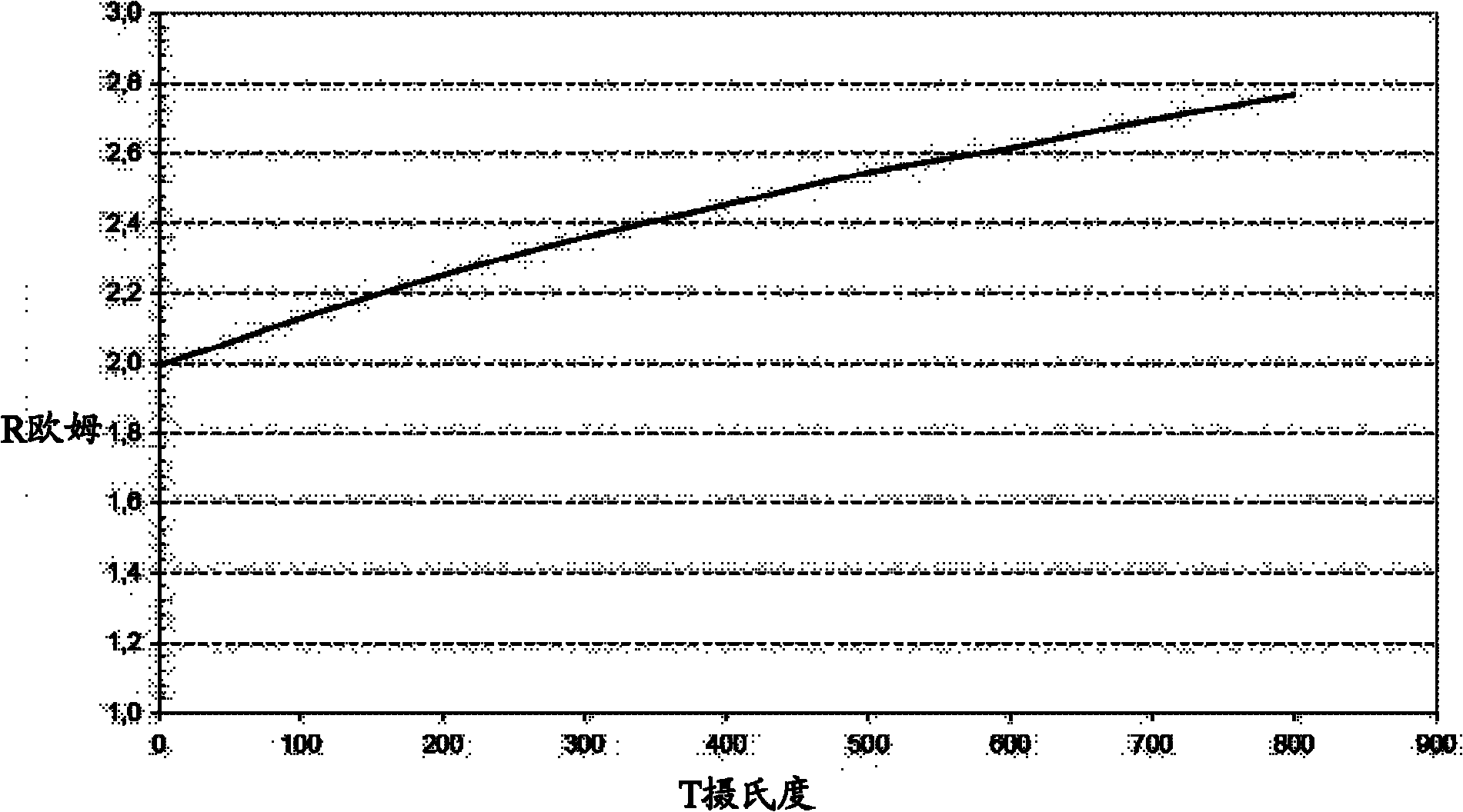
technical field [0001] The invention relates to the field of power electronics, in particular to a braking resistor protection method and equipment for a main circuit of an electric train. Background technique [0002] When the electric train is in the resistance electric braking mode, its kinetic energy will be converted into electrical energy and guided to the braking resistor of the main circuit of the electric train, and the braking resistor will convert the electrical energy into heat energy and consume it. Among them, the temperature of the braking resistor will rise rapidly during the process of consuming electric energy. In practical applications, the temperature of the braking resistor will rapidly rise to about 600 degrees Celsius in a short period of time. In order to prevent the braking resistor from being burned due to overheating, it is usually necessary to install a temperature sensor in the braking resistor box to realize the protection of the braking resisto...

Claims


Application Information

Patent Timeline
IPC IPC(8): H02H7/00H02H5/04
Inventor 许宁吴能峰王辉华肖禹沈建华杨北辉
Owner SHENZHEN INVT TRANSPORTATION TECH CO LTD
Learn More