Pulse detonation cleaning unit with multiple folded flow paths

A cleaning device and pulse detonation technology, which is applied in the direction of cleaning heat transfer devices, descaling devices, combustion cleaning, etc., can solve the problems of not interfering with boilers, etc.

Inactive Publication Date: 2011-12-14
PARKER HANNIFIN CORP
View PDF8 Cites 4 Cited by
  • Summary
  • Abstract
  • Description
  • Claims
  • Application Information

AI Technical Summary

Problems solved by technology

In addition, this cleaning system should not interfere with the operation of the boiler

Method used


Image

  • Pulse detonation cleaning unit with multiple folded flow paths
  • Pulse detonation cleaning unit with multiple folded flow paths
  • Pulse detonation cleaning unit with multiple folded flow paths

Examples


Embodiment Construction

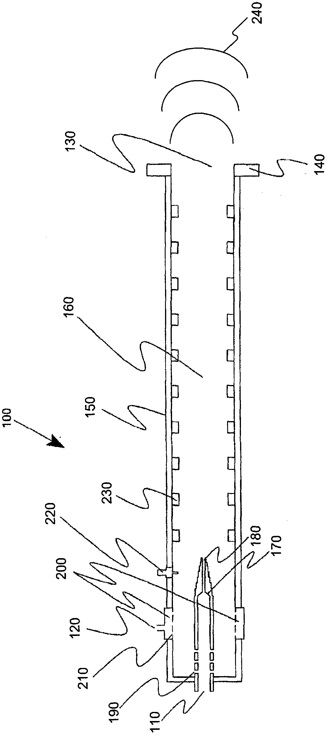
[0036] As used herein, the term "pulse detonation combustor" ("PDC") refers to a device or system that uses detonation or quasi-detonation of fuel and oxidant to produce both a pressure rise and a velocity increase. The PDC can be operated in a repetitive mode to generate multiple detonations or quasi-detonations within the device. "Detonation" may be ultrasonic combustion, in which shock waves are coupled into the combustion zone. The shock can be maintained by the energy released from the combustion zone to cause the products of combustion to be at a higher pressure than the reactants of combustion. "Quasi-detonation" may be a supersonic turbulent combustion process that produces a higher pressure rise and velocity increase than that produced by an acoustic deflagration wave. For simplicity, as used herein, the term "detonation" or "detonation wave" shall include both detonation and quasi-detonation.

[0037] Exemplary PDCs, some of which are discussed in more detail below...


PUM


Abstract

The present application relates to pulsed detonation cleaning devices having multiple folded flow paths. The present application provides a pulse detonation cleaning device (250). The pulse detonation cleaning device (250) may include: an air inlet (110), a fuel inlet (120), an ignition device for generating a detonation wave (240) in communication with the air inlet (110) and the fuel inlet (120) (220), a plurality of folded flow paths (260) in communication with the ignition device (220), and a plurality of flow diverting devices (280, 300) positioned in the folded flow around the diameter (260), thereby causing the detonation wave (240) to reverse direction multiple times.

Description

technical field [0001] The present application relates generally to pulse detonation cleaning devices and, more particularly, to periodic pulse detonation cleaning devices having a multiple folded flow path extending therethrough. Background technique [0002] Industrial boilers operate by using a heat source to generate steam from water or another type of working fluid. The steam can be used to drive turbines or other types of loads. The heat source may be a burner in which a fuel-air mixture is burned. Heat may be transferred from the combustor to the working fluid through a heat exchanger. However, burning the fuel-air mixture can create residues on the surfaces of burners, heat exchangers, and the like. This deposition of soot, ash, slag or dust on the heat exchanger surfaces inhibits efficient transfer of heat to the working fluid. This decrease in efficiency can be reflected by an increase in exhaust temperature from the back end of the process and an increase in f...

Claims


Application Information

Patent Timeline
Patent Type & Authority Applications(China)
IPC IPC(8): F23J1/00F23J3/00
CPCF28G7/00F23M9/06F28G7/005B08B7/0007F23R7/00F23D14/62F23J3/023F23C2900/03005F27D25/00F23C15/00F23J3/02F27D25/006F28G11/00
Inventor T·X·张D·M·查平M·A·佩列戈伊
Owner PARKER HANNIFIN CORP
Why Eureka
Try Eureka