
Power transmission device and non-contact power transmission system

A conveying device, non-contact technology, applied in transmission systems, near-field transmission systems, circuit devices, etc., can solve the problem of inability to transmit large electric energy by the electric energy receiving coil, and achieve the improvement of electric energy transmission efficiency, enhancement of magnetic coupling, and reduction of impedance. Effect

Inactive Publication Date: 2011-12-07
TOKIN CORP
View PDF4 Cites 4 Cited by
  • Summary
  • Abstract
  • Description
  • Claims
  • Application Information

AI Technical Summary

Problems solved by technology

[0005] However, if the power transmission coil is incorporated into the feedback loop of the switching element, large power cannot be transmitted from the power transmission coil to the power reception coil

Method used


Image

  • Power transmission device and non-contact power transmission system
  • Power transmission device and non-contact power transmission system
  • Power transmission device and non-contact power transmission system

Examples


no. 1 approach

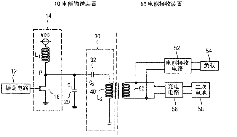
[0018] refer to figure 1 It can be seen that the non-contact power transmission system according to the first embodiment of the present invention includes: a power transmission device 10 having a power transmission coil 40 ; and a power receiving device 50 having a power receiving coil 60 . That is, the power transmitting coil 40 and the power receiving coil 60 can be separated from each other.

[0019] In the non-contact power transmission system of this embodiment, by disposing the power receiving coil 60 of the power receiving device 50 at a predetermined position near the power transmission coil 40, the electromagnetic induction between the power receiving coil 60 and the power transmission coil 40 is used to generate The power transmission device transmits power to the power receiving device. Here, the power receiving device 50 is, for example, a portable electronic device, and the power transmission device 10 is, for example, a charging stand or a bracket of the portabl...

no. 2 approach

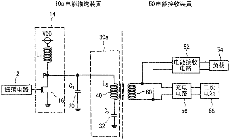
[0043] refer to image 3 The non-contact power transmission system of the second embodiment of the present invention is a modified example of the non-contact power transmission system of the above-mentioned first embodiment, except that the configuration of the power derivation circuit 30a in the power transmission device 10a is different from that of the above-mentioned first embodiment. A non-contact power transmission system according to one embodiment has the same configuration. Therefore, the different electric energy deriving circuits 30a will be specifically described below, and descriptions of other contents will be omitted.

[0044] The electric energy derivation circuit 30a of this embodiment has the electric energy transmission coil 40 connected to the output point P, and the 2nd capacitor 32 connected between the electric energy transmission coil 40 and ground (second fixed potential). That is, the electric energy deriving circuit 30a is also formed by connecting ...


PUM

PropertyMeasurementUnit
inductanceaaaaaaaaaa
thicknessaaaaaaaaaa

Abstract

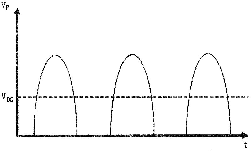
A system for transmitting electric power from an electric power transmission apparatus (10) to an electric power reception apparatus (50) by using electromagnetic induction between a power receiving coil (60) and a power transmitting coil (40). The electric power transmission apparatus (10) comprises an electric power switching circuit (14), a first capacitor (20) and an electric power derivation circuit (30). The electric power switching circuit (14) includes a switching element (16) and an output point (P) and switches the switching element (16) at a predetermined switching frequency (f), thereby causing the electrical potential at the output point (P) to exhibit a predetermined variation, wherein the predetermined variation is an electrical potential variation obtainable by the half-wave rectification of a sinusoidal wave variation which has a predetermined amplitude. The first capacitor (20) is coupled between the output point (P) and a first constant electrical potential (ground). The electric power derivation circuit (30) includes the power transmission coil (40) and is formed to cause an AC variation of the foregoing predetermined variation to occur between the both ends of the power transmission coil (40). The electric power derivation circuit (30) is coupled between the output point (P) and a second constant electrical potential (ground).

Description

technical field [0001] The present invention relates to a non-contact power transmission system comprising a power receiving device with a power receiving coil, and a power transmission device with a power transmission coil. In the non-contact power transmission system, by arranging the power receiving coil of the power receiving device at a specified position near the power transmission coil of the power transmission device, the electromagnetic induction between the power receiving coil and the power transmission coil is used to generate electricity from the power transmission device. Deliver power to the power receiving device. For example, the power receiving device is a portable electronic device such as a portable phone or a portable music player, and the power transmitting device is a charging stand or a cradle for the portable electronic device. Background technique [0002] In the power transmission device, the power transmission coil is driven by a power switching ...

Claims


Application Information

Patent Timeline
Patent Type & Authority Applications(China)
IPC IPC(8): H02J7/10H01M10/46H02J7/00H02J17/00H02M3/28
CPCH01M10/46H02M3/28H02J7/025H02J17/00Y02E60/12H02J50/10H02J7/0068Y02E60/10H02J50/12H02J50/005H04B5/0037
Inventor 若生直树冈利昭
Owner TOKIN CORP
Learn More