


Quick Research
Generate reliable direction feasibility study reports for your R&D in just a few steps.

Technical Q&A
Discover and master advanced knowledge NOW. Basics, ideas, possibilities, all at once.

Find Solutions
As an expert in R&D theories, this can generate solutions to your technical problems instantly.

Evaluate Feasibility
Analyze your overall solution with one click, know your potential R&D risks in advance.

Monitor Landscape
Get weekly tech updates, stay abreast of the latest tech innovations and key insights.
pipe clamping ring
A technology for clamping rings and pipes, which is applied in the field of clamping elements of pipeline fittings, pipeline fittings and pipeline joints, and can solve problems such as impracticability and difficulty
- Summary
- Abstract
- Description
- Claims
- Application Information
AI Technical Summary
Problems solved by technology
Method used
Image


Examples
Embodiment Construction
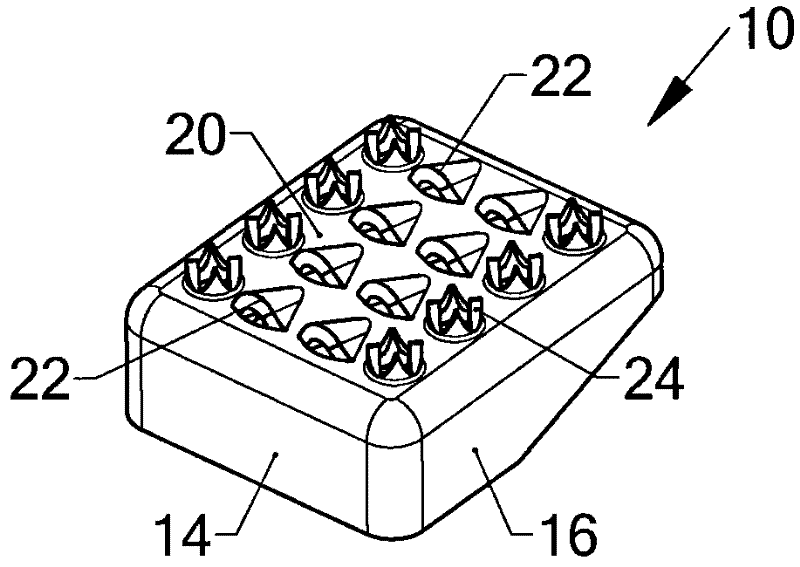
[0031] figure 1 and figure 2 A clamping element 10 made of sheet steel is shown. figure 1 The interior of the clamping element is shown, wherein all walls 12 , 14 , 16 , 18 of the element can be seen. exist figure 2 In , an array of two different sizes of teeth can be seen. The angled side walls 12, 16 give the element 10 a wedge-shaped configuration. The exposed top exterior surface 20 is steel plate which is integral with all four walls.
[0032] The clamping element 10 is provided with an array of large clamping teeth 22 and small clamping teeth 24 . The sharp sides of all teeth 22 , 24 face the higher of the two end walls 14 , the larger teeth 22 projecting more from the surface of the top outer surface 20 than the smaller teeth 24 .
[0033] With reference to the remaining figures, like reference numerals are used to denote like parts.
[0034] image 3 Clamping ring 26 is shown for use in reference to Figure 4 used in the pipe fittings described. The ring ...
PUM
 Abstract
Description
Claims
Application Information
 - R&D Engineer
- R&D Manager
- IP Professional
- Industry Leading Data Capabilities
- Powerful AI technology
- Patent DNA Extraction
Browse by: Latest US Patents, China's latest patents, Technical Efficacy Thesaurus, Application Domain, Technology Topic, Popular Technical Reports.
© 2024 PatSnap. All rights reserved.Legal|Privacy policy|Modern Slavery Act Transparency Statement|Sitemap|About US| Contact US: help@patsnap.com