
Tower fan air channel swing mechanism

A technology of rotating mechanism and air duct, applied in the field of rotating mechanism of tower fan air duct, can solve the problems such as the influence of fuselage rotation on safety, poor structural strength, unreasonable structure, etc., to avoid the hidden danger of long-term torsional wear, improve reliability, reduce load effect

Inactive Publication Date: 2013-05-08
MIDEA GRP CO LTD
View PDF6 Cites 0 Cited by
  • Summary
  • Abstract
  • Description
  • Claims
  • Application Information

AI Technical Summary

Problems solved by technology

[0002] There are three types of tower fan oscillating air supply mechanisms in the market: one is that the fuselage oscillates relative to the base. Body weight, long-term use and reliable travel, and the rotation of the entire body is prone to external resistance interference, which affects safety, and the long-term torsion and wear of the power cord also poses safety hazards
The second type is a mechanism that rotates the air duct inside the tower fan to control the air supply. However, such products currently on the market fix the swing mechanism at the lower end of the wind wheel and behind the motor. The connection span between the swing mechanism and the air duct is long and the strength is low. , poor reliability, and due to the long arm and poor structural strength, it can only be designed as an air duct assembly; also because the control panel is on the top of the fuselage, and the synchronous motor is at the bottom of the fuselage, so there must be a long connecting line running through the fuselage Connection, unreasonable structure, high cost of line length
The three existing tower fan ducts on the market are the components of the duct main body and the duct shaft. The front end of the duct is fixed by the duct shaft and the wind wheel bearing assembly. Wheels cannot share one bearing assembly, which is costly

Method used


Image

  • Tower fan air channel swing mechanism
  • Tower fan air channel swing mechanism
  • Tower fan air channel swing mechanism

Examples


Embodiment Construction

[0020] The novelty of the present invention will be further described below in conjunction with the accompanying drawings and embodiments.

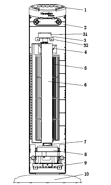
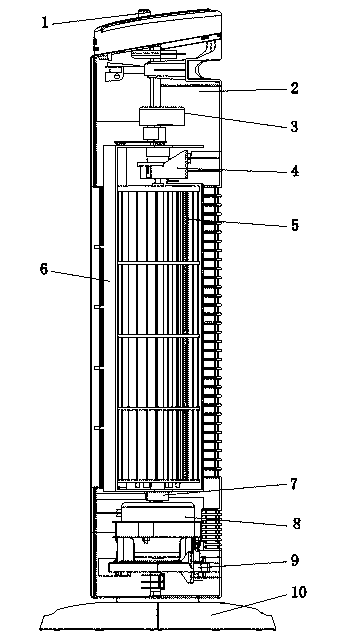
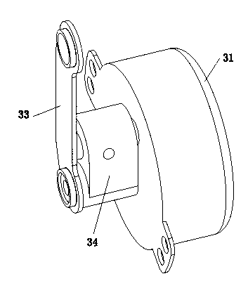
[0021] Such as Figures 1 to 9 As shown, it is a tower fan air duct rotation mechanism, including a casing 2, a control panel 1 arranged at the upper end of the casing 2, a wind wheel bearing assembly 4, a wind wheel 5, an air duct 6, a driving motor 8 and a base 10 The casing 2 includes a front casing 22 and a rear casing 21 that cooperate with each other, and an outlet grille is arranged on the front casing 22; an upper shaft 51 is arranged on the upper end of the wind wheel 5, and a lower shaft is arranged on the lower end The shaft 52 and the wind wheel 5 are located in the air duct 6; the feature of the present invention is that it also includes a swing mechanism 3, and the swing mechanism 3 is installed above the inside of the casing 2, close to the control panel 1, thus shortening the distance between the control panel and the swin...


PUM


Abstract

The invention relates to a tower fan air channel swing mechanism which comprises an enclosure, a control panel, a wind wheel bearing assembly, a wind wheel, an air channel, a driving motor and a base, wherein the control panel is arranged at the upper end of the enclosure; the enclosure comprises a front housing and a rear housing which are matched mutually, and the front housing is provided withan air-out grating; the upper end of the wind wheel is provided with an upper shaft, the lower end of the wind wheel is provided with a lower shaft, and the wind wheel is positioned in the air channel; the mechanism is characterized by also comprising a wabble mechanism which is installed at the upper part in the enclosure and drives the air channel to rotate; the air channel is provided with an air inlet and an air outlet; the inner side at the upper end of the air channel is provided with a front shaft hole, and the outer side at the lower end of the air channel is provided with a rear shaft hole; the wind wheel bearing assembly is installed on the upper part in the enclosure and is positioned between the air channel and the wind wheel; the upper end of the wind wheel bearing assembly is matched with the front shaft hole; the upper shaft of the wind wheel is positioned in the wind wheel bearing assembly and can rotate; the lower shaft of the wind wheel passes through the rear shaft hole, can rotate and is connected with a rotary shaft of the driving motor; and the enclosure is fixed on the base. According to the invention, the connection distance of the wabble mechanism and the air channel is reduced greatly, the reliability is improved, the line length between the wabble mechanism and the control panel is shortened, the air channel and the wind wheel bearing assembly are optimized, and the cost is lowered.

Description

technical field [0001] The invention relates to a tower fan air duct rotation mechanism, in particular to an air duct rotation mechanism for a cross-flow tower fan. Background technique [0002] There are three types of tower fan oscillating air supply mechanisms in the market: one is that the fuselage oscillates relative to the base. Body weight, long-term use and reliable travel, and the rotation of the entire body is prone to external resistance interference, which affects safety, and the long-term torsional wear of the power cord also poses safety hazards. The second type is a mechanism that rotates the air duct inside the tower fan to control the air supply. However, such products currently on the market fix the swing mechanism at the lower end of the wind wheel and behind the motor. The connection span between the swing mechanism and the air duct is long and the strength is low. , poor reliability, and due to the long arm and poor structural strength, it can only be d...

Claims


Application Information

Patent Timeline
Patent Type & Authority Patents(China)
IPC IPC(8): F04D25/10
Inventor 王俊杰黄敏荣
Owner MIDEA GRP CO LTD
Learn More