Drill assembly and system and method for forming a pilot hole

A drilling machine and component technology, used in bone drill guidance, medical science, surgery, etc., can solve the problems of unsatisfactory, expensive, and complicated technology, and achieve the effect of reasonable cost.

Inactive Publication Date: 2011-11-23
DGIMED ORTHO INC
View PDF1 Cites 5 Cited by
  • Summary
  • Abstract
  • Description
  • Claims
  • Application Information

AI Technical Summary

Problems solved by technology

However, this approach is often relatively complex and may require additional electronics and visual displays for surgery
This technique may require specialized training and / or machine operators and can be relatively expensive
Therefore, these techniques are not ideal in the crowded space of an operating room, especially when it is desired to minimize the amount of equipment and personnel involved in the procedure

Method used


Image

  • Drill assembly and system and method for forming a pilot hole
  • Drill assembly and system and method for forming a pilot hole
  • Drill assembly and system and method for forming a pilot hole

Examples


Embodiment Construction

[0029] The embodiments of the invention described below are not intended to be exhaustive or to limit the invention to the precise forms disclosed in the following detailed description. Rather, these embodiments were chosen and described so that others skilled in the art can appreciate and understand the principles and practice of the invention.

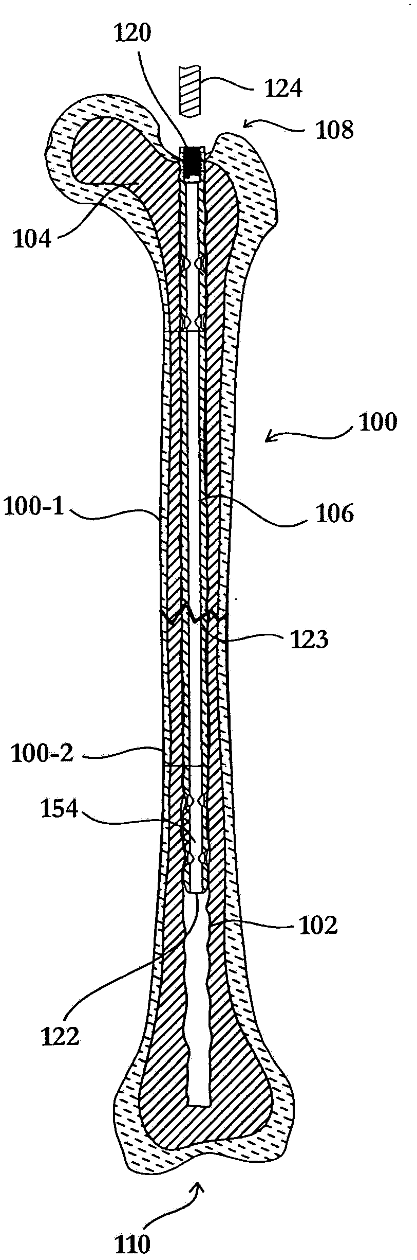
[0030] Referring now to the drawings, wherein like reference numerals are used to designate these parts throughout the drawings, first reference figure 1 , shows a cross-sectional view of two portions 100-1 and 100-2 of a fractured femur. Although the fracture is generally shown as a neat break 123 in both parts of the bone, the femur 100 may also be broken into many smaller bone pieces or damaged in some other way. Therefore, it should be understood that the devices and methods described herein for two bone blocks can also be applied to three or more bone blocks or bone fragments, or even broken bones that have not been divided int...


PUM


Abstract

A drill assembly comprises a motor guide tube, an adaptor extending from a distal end of the motor guide tube, an elongate drill guide tube extending from a distal end of the adaptor, a retractable guide tube including an arcuate distal end slideably disposed within a channel of the drill guide tube, an actuation lever operably coupled to the retractable guide tube and extending from an outer surface of the adaptor, a flexible drill cable slideably disposed within the retractable guide tube, a drill motor operably coupled to the flexible drill cable, and a push-pull cable extending between the drill motor at a distal end and a liner stage motor inside a control box at a proximal end. A distal end of the flexible drill cable is structured to be advanced through the arcuate distal end of the retractable guide tube, and the linear stage motor is operable to advance and retract the push-pull cable and the drill motor.

Description

technical field [0001] The present invention relates to flexible cutting tools and, more particularly, to drill assembly systems and methods for drilling pilot holes from the internal passage of an intramedullary rod or nail. Background technique [0002] Intramedullary rods are commonly used in orthopedic surgery for rods to breaks in long bones of the extremities, such as the femur and tibia. These rods are used to straighten and stabilize broken or fractured bones, and to maintain proper alignment of the bone fragments relative to each other during the healing process. In addition, the intramedullary rod can provide strength to the bone during the patient's recovery period. One common surgical rod implantation procedure involves drilling the medullary canal of the fractured bone from the proximal end to the distal end of the bone and inserting the intramedullary rod into the evacuated space. In order to maintain the proper relationship between the intramedullary rod and...

Claims


Application Information

Patent Timeline
Patent Type & Authority Applications(China)
IPC IPC(8): A61B17/17
CPCA61B2017/00212A61B17/1631A61B17/1725A61B17/164
Inventor 拉蒙·B·古斯蒂洛帕特里克·R·科尔内尔勒祖德·L·萨辛戈杰里米·J·林
Owner DGIMED ORTHO INC
Why Eureka
Try Eureka