
Vertical guide rail automatic cloth conveying device for transfer printing machine

A transfer printing, vertical technology, applied in the direction of rotary printing machine, printing machine, transfer printing, etc., can solve the problems of pattern deformation, uneven coloring, etc. compact effect

Active Publication Date: 2011-11-23
NEWTECH TEXTILE TECH DEV SHANGHAI
View PDF6 Cites 16 Cited by
  • Summary
  • Abstract
  • Description
  • Claims
  • Application Information

AI Technical Summary

Problems solved by technology

[0003] In order to solve the problems of weft skew, weft arc, unexpected elongation, uneven coloring, and pattern deformation when the fabric conveying device of the existing transfer printing machine adopts the guide roller support cloth conveying method, the padding machine directly conveys the cloth, and the flat horizontal guide rail. and other shortcomings, the present invention provides a vertical guide rail cloth feeding device for transfer printing machines, which can overcome the shortcomings of the above-mentioned cloth feeding methods, and can achieve stable tension, small accidental elongation, small weft skew and The weft arc and flat running state will transport the printed fabric to the transfer printing area to ensure the fabric has a small tension, flat and consistent width during the printing process, and the transfer quality is stable

Method used


Image

  • Vertical guide rail automatic cloth conveying device for transfer printing machine
  • Vertical guide rail automatic cloth conveying device for transfer printing machine
  • Vertical guide rail automatic cloth conveying device for transfer printing machine

Examples


Embodiment Construction

[0049] The following is an embodiment according to the present invention and described in conjunction with the accompanying drawings, which is a vertical guide rail automatic cloth conveying device used on a cold transfer printing machine. However, the present invention is not limited to the described embodiments, and various modifications can be made by those skilled in the art within the scope of the inventive concept and the protection defined by the claims.

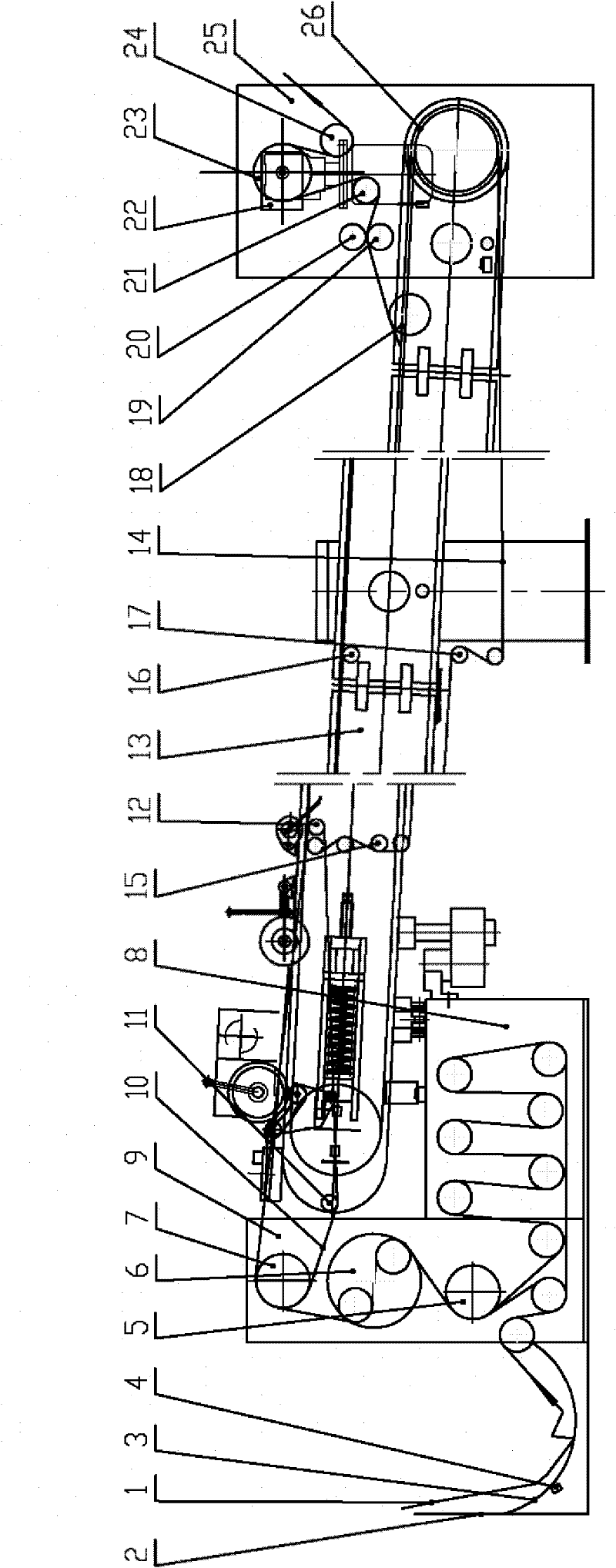
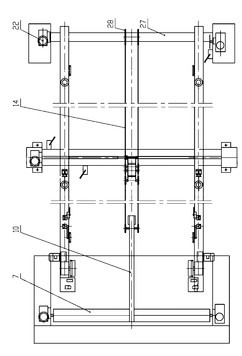
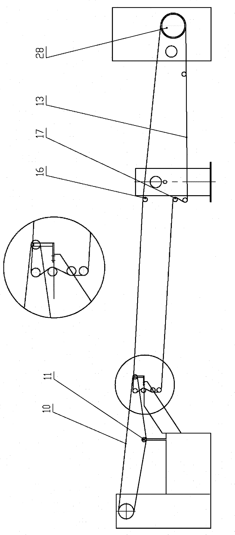
[0050] Such as figure 1 , figure 2 with image 3 As shown, the vertical guide rail automatic cloth feeding device of the transfer printing machine includes a cloth storage device 2, a head box 9, a cloth feeding device 13 and a tail box 25 connected in sequence, and is fixedly connected to the left and right sides before the transfer printing device of the transfer printing machine. on the rack and connected to the automatic control system. The head box 9 is composed of a weft adjusting device 8 and an overfeeding...


PUM


Abstract

The invention discloses a vertical guide rail automatic cloth conveying device for a transfer printing machine. The device comprises a cloth storage device, a headstock box, a cloth conveying device and a tailstock box, wherein a weft adjustment device and an overfeed device are arranged in the headstock box; the cloth conveying device consists of a vertical guide rail cloth flatly-conveying system and a fabric carrying device; an active pin miss device, an active cloth feeding device and two sets of tension detection devices are arranged in the tailstock box; the weft adjustment device is positioned on the rear lower side of the headstock box; the overfeed device is positioned in the middle of the headstock box and consists of an upper overfeed device, a lower overfeed device and a widthexpansion device; the vertical guide rail cloth flatly-conveying system comprises a vertical guide rail and a pin plate conveying chain and is used for supporting the two sides of a fabric; the fabric carrying device consists of a cloth carrying flat belt part and a rope-shaped cloth carrying belt part and is used for supporting the middle part of the fabric; the active pin miss device consists of an active pin miss wheel and an active pin miss roller and is used for stripping the fabric from the pin plate; the active cloth feeding device consists of an active cloth feeding roller, a drive motor and a speed reducer; and each set of tension detection device consists of a tension sensor and a tension roller.

Description

technical field [0001] The invention relates to a printing and dyeing machine in a textile machine, in particular to a vertical guide rail automatic cloth feeding device of a transfer printing machine. According to the process requirements of transfer printing (especially cold transfer printing), during the transfer printing process, the fabric needs to be kept loose, flat, without tension, without weft skew and weft arc when entering the transfer area. The warp and weft density and width must meet the specified specifications and sizes, so as to ensure that the pattern of the fabric will not be deformed after printing and the dye distribution will be uniform. Background technique [0002] Transfer printing technology is a new type of printing method. Its main feature is energy saving and environmental protection. The process is to print the dye on the transfer paper according to the designed pattern, and then use physical (pressurization, heating) or chemical (Auxiliary re...

Claims


Application Information

Patent Timeline
IPC IPC(8): B41F16/02B41F13/02
Inventor 钟博文
Owner NEWTECH TEXTILE TECH DEV SHANGHAI
Learn More