
Swivel joint and rotary table using same

A technology of rotary workbench and rotary joint, which is applied in the direction of workbench, manufacturing tools, machine platform/support, etc. It can solve the problems that affect the use, the rotary joint only supports single channel, and the pipes are twisted together.

Inactive Publication Date: 2011-11-09
HONG FU JIN PRECISION IND (SHENZHEN) CO LTD +1
View PDF4 Cites 15 Cited by
  • Summary
  • Abstract
  • Description
  • Claims
  • Application Information

AI Technical Summary

Problems solved by technology

[0003] However, the above-mentioned rotary joints generally only support a single channel. If there are multiple workstations, multiple supply pipes and multiple rotary joints need to be installed. During the work process, the pipes are easily twisted together, which affects the use.

Method used


Image

  • Swivel joint and rotary table using same
  • Swivel joint and rotary table using same
  • Swivel joint and rotary table using same

Examples


Embodiment Construction

[0015] The rotary joint and the rotary table using the rotary joint of the present invention will be further described in detail below in conjunction with the accompanying drawings and embodiments.

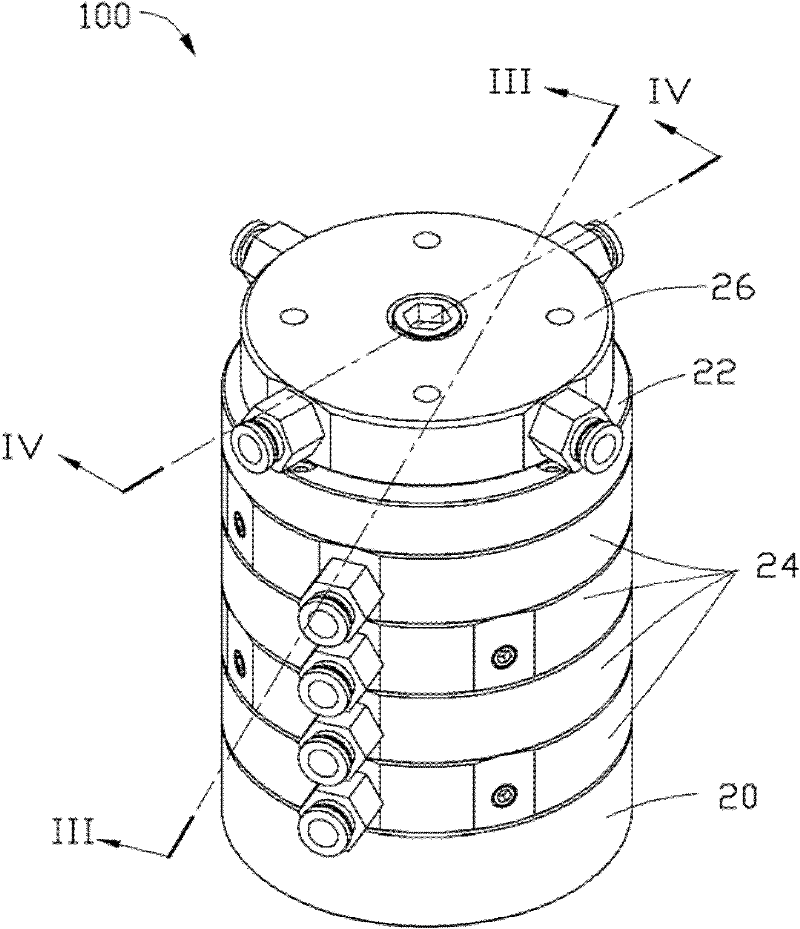
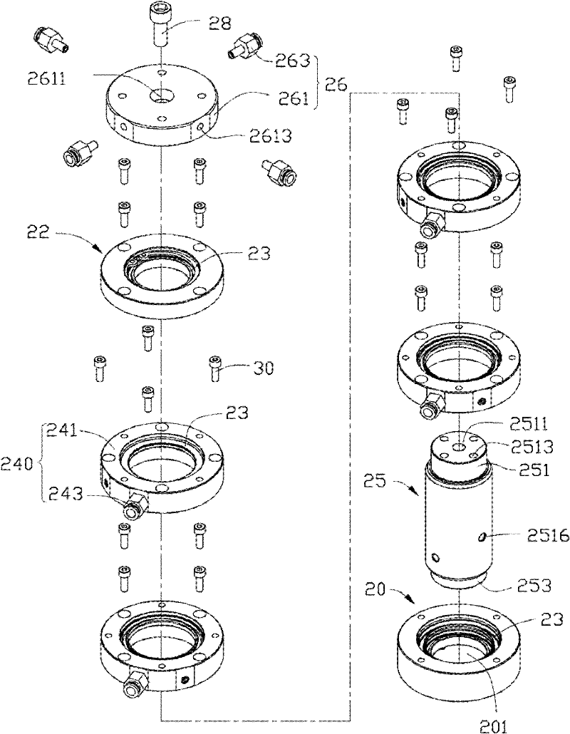
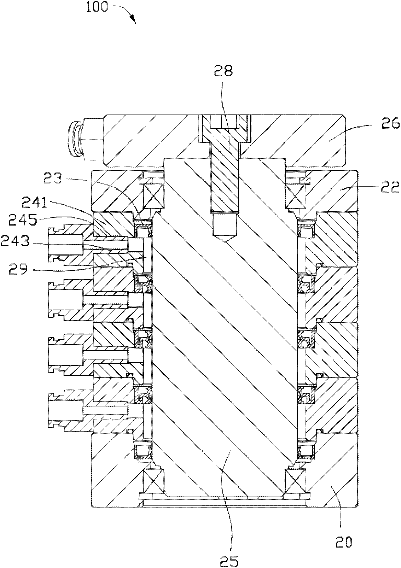
[0016] See figure 1 and figure 2 , The rotary joint 100 of the present invention includes a lower cover 20 , an upper cover 22 , a plurality of annular seals 23 , an input assembly 24 , a rotating shaft 25 , an output member 26 and a locking member 28 . The lower cover 20 , the upper cover 22 and the input assembly 24 are all provided with sealing elements 23 . The lower cover 20 and the upper cover 22 are respectively located on two sides of the input assembly 24 , and are arranged on the rotating shaft 25 together with the input assembly 24 . The locking member 28 fixes the output member 26 on one end of the rotating shaft 25 . In this embodiment, the locking member 28 is a screw.

[0017] The lower cover 20 has a circular shape, and a shaft hole 201 for installing a rotatin...


PUM


Abstract

The invention provides a swivel joint, which comprises an input assembly, an output component which can rotate with respect to the input assembly, a spindle and a sealing element. The input assembly comprises input components which are provided with a socket hole, and an output hole is arranged on the output component. The number of the input components is at least two. The input components are rotatably sleeved on the rotating shaft, and at least two input components are axially arranged in parallel along the spindle. Inner walls of the at least two input components, an outer wall of the spindle and the sealing element together form a ring channel communicated with the socket hole. A feed hole for communicating the channel with the output hole of the output component is arranged in the spindle. The number of the feed hole and the output hole is corresponding to the number of the input components. Each feed hole has an opening on the spindle hole. Each opening is communicated with a corresponding input component channel. Openings of the plurality of feed holes are axially distributed at interval along the spindle. The invention further provides a rotating table using the swivel joint.

Description

technical field [0001] The invention relates to a rotary joint, in particular to a rotary joint for connecting pipelines and a rotary worktable using the rotary joint. Background technique [0002] A rotary workbench comprises a base, a turntable set on the base, a work station set on the turntable, a supply pipeline and a rotary joint set on the supply pipeline. The supply pipeline is connected to the workstation and external fluid supply sources such as gas or liquid to maintain the normal operation of the workstation. The rotary joint includes an input piece and an output piece. An output hole is opened on the output piece, and an input hole is opened on the input piece. The output piece is rotatably mounted on the input piece. The input hole and the output hole can also be kept in communication when the rotary joint rotates. In this way, when the turntable rotates, The fluid supply source can also continuously supply liquid or gas to the workstation to maintain the nor...

Claims


Application Information

Patent Timeline
Patent Type & Authority Applications(China)
IPC IPC(8): F16L39/06F16M11/02B25H1/02
CPCF16M11/18F16L39/06F16M11/08B25H1/02
Inventor 刘振星刘大伟
Owner HONG FU JIN PRECISION IND (SHENZHEN) CO LTD
Learn More