
Method and system for calibrating electric energy meter and electric energy meter

A technology of calibration system and electric energy meter, which is applied in the field of electric power, can solve the problems of hardware resources and multiple calibration steps, and achieve the effect of less hardware resources, reduced quantity, and reduced calibration steps

Inactive Publication Date: 2011-11-02
SHENZHEN RENERGY TECH
View PDF4 Cites 22 Cited by
  • Summary
  • Abstract
  • Description
  • Claims
  • Application Information

AI Technical Summary

Problems solved by technology

[0032] The purpose of the embodiments of the present invention is to provide a method for correcting the gain of an electric energy meter, which aims to solve the problem that the existing technical solutions require more hardware resources and correction steps

Method used


Image

  • Method and system for calibrating electric energy meter and electric energy meter
  • Method and system for calibrating electric energy meter and electric energy meter
  • Method and system for calibrating electric energy meter and electric energy meter

Examples


Embodiment Construction

[0051] In order to make the objectives, technical solutions and advantages of the present invention clearer, the following further describes the present invention in detail with reference to the accompanying drawings and embodiments. It should be understood that the specific embodiments described herein are only used to explain the present invention, but not to limit the present invention.

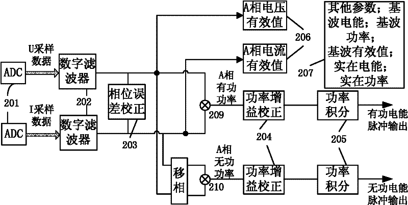
[0052] The invention provides a method for calibrating an electric energy meter. The method is as image 3 As shown, the method is completed by an electric energy meter and includes the following steps:

[0053] S31. Perform phase correction and gain correction on the current and voltage signals after digital filtering;

[0054] S32. Input the electrical signal that completes the phase correction and gain correction into the parameter module of the electric energy meter.

[0055] It should be noted that the above parameter modules can be: active power, reactive power, apparent power, voltage effec...


PUM


Abstract

The invention is suitable for the field of electric power, and provides a method and system for calibrating an electric power meter and the electric power meter. The method comprises the following steps of: performing phase calibration and gain calibration on current and voltage signals which are subjected to digital filtration; and inputting electric signals which are subjected to phase calibration and gain calibration into a parameter module of the electric power meter. The technical scheme of the invention has the advantages of reduction in calibrating steps and small quantity of hardware resources.

Description

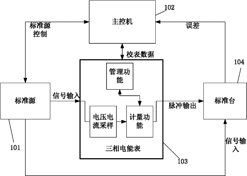
Technical field [0001] The invention belongs to the field of electric power, and in particular relates to a correction method, system and electric energy meter of an electric energy meter. Background technique [0002] The electric energy meter must correct the active energy accuracy or the reactive energy accuracy during the production process, and the errors that need to be corrected include gain error and phase error. The block diagram of the current general correction system is as figure 1 (Take a three-phase electric energy meter as an example): Including: standard source 101, main control machine 102, three-phase electric energy meter 103 and standard station 104; [0003] Among them, the standard source 101: output a standard AC voltage and current signal as the standard signal source of the electric energy meter calibration system; [0004] Main control machine 102: As the main control of the entire calibration system, it is responsible for managing the data transmission bet...

Claims


Application Information

Patent Timeline
Patent Type & Authority Applications(China)
IPC IPC(8): G01R35/04G01R22/06
Inventor 苗书立刘凯
Owner SHENZHEN RENERGY TECH
Learn More