Rope reeving structure for crane

A crane and steel cable technology, which is applied to cranes, trolley cranes, load hanging components, etc., can solve the problems of increased weight, not necessarily high responsiveness, and high manufacturing costs, and achieves simple structure, low cost, high lift and high speed effect

Active Publication Date: 2011-10-19
MITSUI E&S MACHINERY CO LTD
View PDF2 Cites 10 Cited by
  • Summary
  • Abstract
  • Description
  • Claims
  • Application Information

AI Technical Summary

Problems solved by technology

However, the first displacement mechanism is provided with two attenuation oil cylinders facing each other on the connecting rod that holds the free end of the steel cable, and the fan-shaped rods arranged at the two ends of the connecting rod are respectively provided with wire rope force compensation. Cylinders, thus high manufacturing costs
[0006] On the other hand, the additional displacement device (refer to Figure 7 ) operates on only one cable in a set of two, so responsiveness is not necessarily high
Furthermore, Patent Document 3 concentrates on the four corners of the spreader because the lower rollers with the axis toward the longitudinal direction of the spreader and the lower rollers with the axis toward the transverse direction of the spreader (refer to figure 2 ), so the four corners of the special container spreader must be made strong (weight increase)

Method used


Image

  • Rope reeving structure for crane
  • Rope reeving structure for crane
  • Rope reeving structure for crane

Examples


Embodiment approach 2

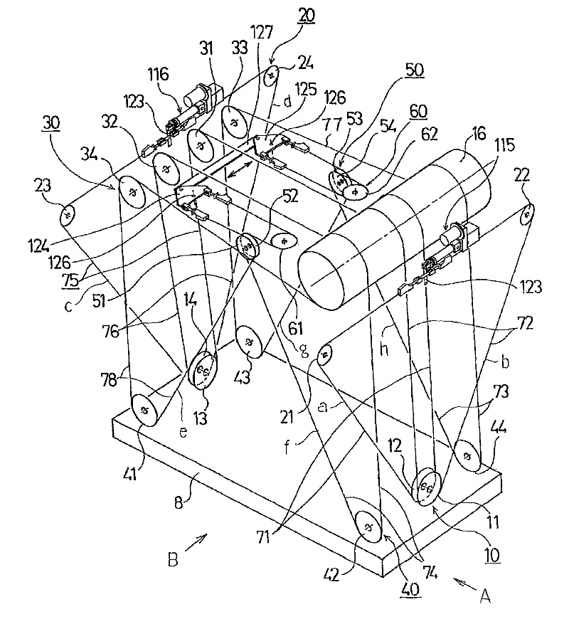
[0076] Next, the second embodiment of the present invention will be described, and the same components as those in the first embodiment will be assigned the same reference numerals and detailed description will be omitted.

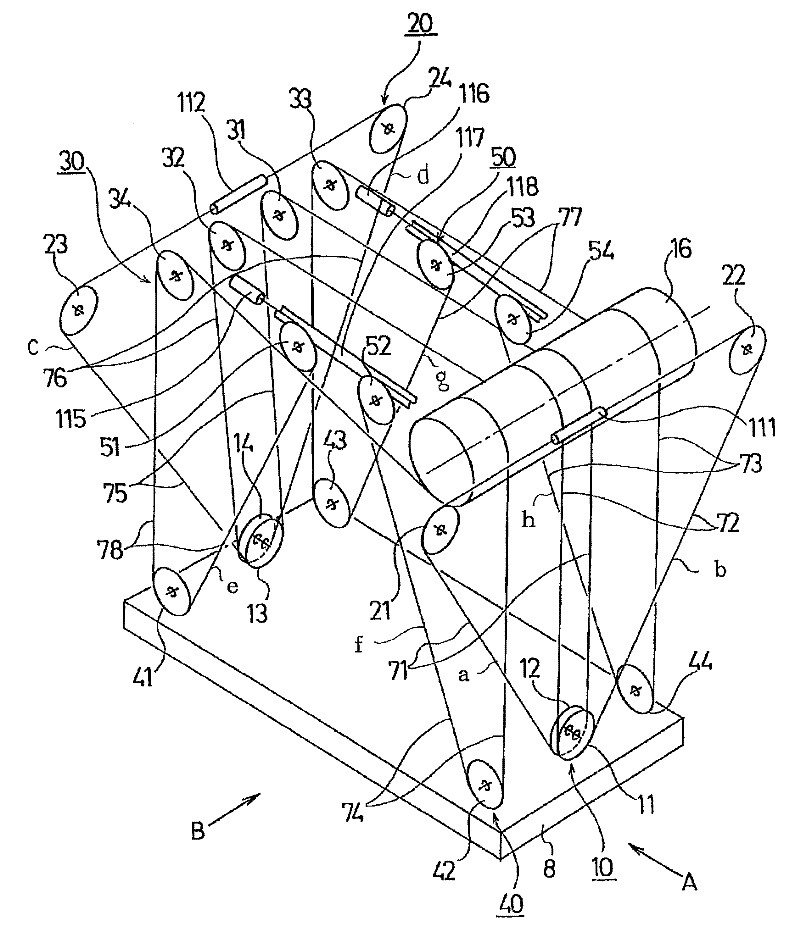
[0077] The first difference is that, if Figure 8 As shown, single-head cylinder-type tilt-twist devices 115 , 116 are used instead of double-head cylinder-type tilt-twist devices 111 , 112 . In this case, the arm 123 arranged on the connecting portion of the first and second steel cables 71, 72 is operated laterally to the spreader 8 by the single-head oil cylinder type tilting and twisting device 115. The head cylinder type tilting and twisting device 116 operates the arm 123 provided on the connecting portion of the fifth and sixth wire ropes 75 and 76 in the lateral direction of the hoisting tool 8 .

[0078] The second difference is that a connecting rod 127 parallel to the horizontal direction of the spreader 8 is set on the crane trolley, and the o...


PUM


Abstract

A rope reeving structure simply constructed, highly responsive, and capable of coping with high lifting height and high speed applications. Two sets of ropes (71, 72, and 75, 76), each set being composed of two ropes (71, 72, or 75, 76), pulled out of a drum (16) are mounted at longitudinally opposite ends of a lifting device (8) such that the ropes (71, 72, and 75, 76) form triangles (a-d) between the lifting device (8) and a trolley (6) and such that the oblique sides (x1 (x5), x2 (x6)) of triangles face directions separating from each other. Two sets of ropes (74, 78, and 73, 77), each set being composed of two ropes (74, 78, or 73, 77), pulled out of the drum (16) are mounted at lateral opposite ends of the lifting device (8) such that the ropes (74, 78, and 73, 77) form triangles (e-h) between the lifting device (8) and the trolley (6) and such that the oblique sides (x8 (x4), x7 (x3)) of triangles face each other. All the triangles (a-h) formed by the ropes (71-78) are in congruence.

Description

technical field [0001] The present invention relates to a steel cable suspension structure of a crane handling containers for marine transportation. Background technique [0002] As a cable hanging structure of a crane for handling containers for marine transportation, there is conventionally known a crane in which steel cables are arranged in a V-shape on at least four cable hanging imaginary surfaces constituting the side surfaces of an imaginary inverted pyramid. A wire structure, or a tilting and twisting device of a cable-suspended lifting beam (for example, refer to Patent Document 1 or 2). Also known is a cargo-handling lifting device in which cables are arranged in a truss shape on at least four virtual cable-hanging planes constituting side surfaces of a virtual cuboid (for example, refer to Patent Document 3). [0003] The stringing structure described in Patent Document 1 is said to hardly cause the container to sway, but due to restrictions on haulage, a lifting...

Claims


Application Information

Patent Timeline
Patent Type & Authority Applications(China)
IPC IPC(8): B66C13/06
CPCB66C13/06B66C19/007
Inventor 栢菅信哉
Owner MITSUI E&S MACHINERY CO LTD
Why Eureka
Try Eureka