
Method for displaying connection state of communication component in electric equipment and electric equipment

A communication component and connection status technology, applied in telephone communication, color TV parts, TV system parts, etc., can solve problems such as high power consumption, increased power consumption of communication components, failure to turn off communication components, etc., to increase The effect of power consumption

Inactive Publication Date: 2011-10-19
LENOVO (BEIJING) LTD
View PDF5 Cites 15 Cited by
  • Summary
  • Abstract
  • Description
  • Claims
  • Application Information

AI Technical Summary

Problems solved by technology

[0004] In the process of implementing the present invention, the inventor found that the prior art has at least the following defects: Since the communication component is in an idle working state when it is not connected to the device in the environment where the electronic device is located, the power consumption is very low; and the communication component When trying to find / search for devices in the environment and connect to a device in the environment, it is in a normal working state with high power consumption
And because the electronic equipment has no indicator in the process of not connecting and searching for connection, so the user does not know that the communication part is in the process of searching for connection, and cannot turn off the communication part, thereby increasing the power consumption of the communication part

Method used


Image

  • Method for displaying connection state of communication component in electric equipment and electric equipment
  • Method for displaying connection state of communication component in electric equipment and electric equipment
  • Method for displaying connection state of communication component in electric equipment and electric equipment

Examples


Embodiment Construction

[0029] The method and the electronic device according to the embodiments of the present invention will be described below with reference to the accompanying drawings.

[0030] In the following embodiments of the present invention, an electronic device refers to a device capable of communicating with other devices. Particular forms of electronic equipment include, but are not limited to, mobile phones, personal computers, digital cameras, personal digital assistants, portable computers, game consoles, and the like. Electronic devices can communicate with other devices through wireless, wired or a combination of both, including but not limited to Bluetooth, infrared, WiFi, optical cables, network cables, etc.

[0031] An electronic device has a communication part and a display part. A part mainly responsible for performing communication is a communication part through which electronic devices are connected with external devices. Specifically, the electronic device is connected...


PUM


Abstract

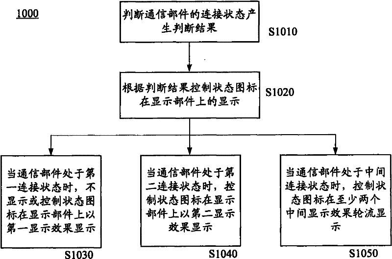
The invention provides a method for displaying the connection state of a communication component in electric equipment and electric equipment. The electric equipment comprises the communication component and a display component and is connected with external equipment by the communication component; the communication component is provided with a first connection state, a second connection state and a middle connection state; and the middle connection state is a process of switching from the first connection state to the second connection state. The method comprises the following steps of: judging the connection state of the communication component and generating a judgment result; controlling the display of a state icon on the display component according to the judgment result; controlling the state icon to be displayed on the display component in a second display result when the judgment result shows that the communication component is in the second connection state; and controlling the state icon to be sequentially or alternately displayed on the display component in at least two middle display results when the judgment result shows that the communication component is in the middle connection state, wherein all middle display effects of the at least two middle display results are different.

Description

technical field [0001] The invention relates to a method for displaying the connection state of a communication component in an electronic device and the corresponding electronic device. Background technique [0002] Currently, various electronic devices including communication parts capable of connecting with external devices are widely used, such as personal computers, digital cameras, portable cellular phones, and portable music players, among others. In such an electronic device, the user can turn on the communication part through a key switch. The electronic device has a state of being connected to a certain device in the environment where the electronic device is located through the communication component, the electronic device is not connected to a device in the environment where the electronic device is located through the communication component, and the electronic device is in the state of being connected to a device in the environment where the electronic device ...

Claims


Application Information

Patent Timeline
Patent Type & Authority Applications(China)
IPC IPC(8): H04M1/725H04M1/247G06F3/048H04N5/225G11C7/16G06F3/0484H04M1/72454H04M1/72466H04M1/72469
Inventor 贺志强张茜
Owner LENOVO (BEIJING) LTD
Learn More