
Large-scale steel wire release device

A pay-off device and steel wire technology, which is applied in transportation and packaging, delivery of filamentous materials, thin material processing, etc., can solve problems such as baffle crushing and damage to the wire pay-off device

Inactive Publication Date: 2011-10-19
JIANGSU SHENWANG GROUP
View PDF10 Cites 16 Cited by
  • Summary
  • Abstract
  • Description
  • Claims
  • Application Information

AI Technical Summary

Problems solved by technology

The steel wire pay-off device set in this way is suitable for the situation where the diameter of the winding steel wire is thin and the total weight of the steel wire is light. If the total weight of the steel wire is heavy, the baffle plate is easy to be crushed, thereby damaging the steel wire pay-off device.

Method used


Image

  • Large-scale steel wire release device
  • Large-scale steel wire release device
  • Large-scale steel wire release device

Examples


Embodiment Construction

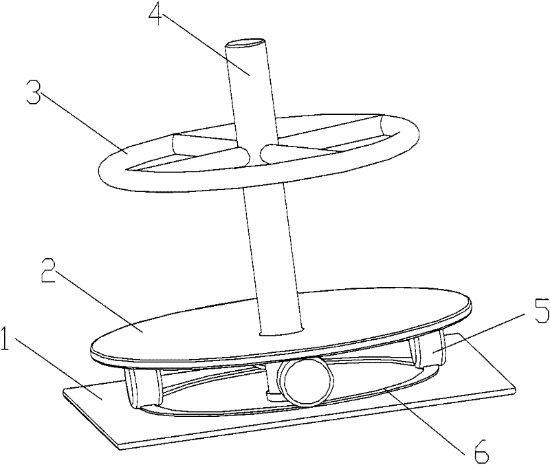
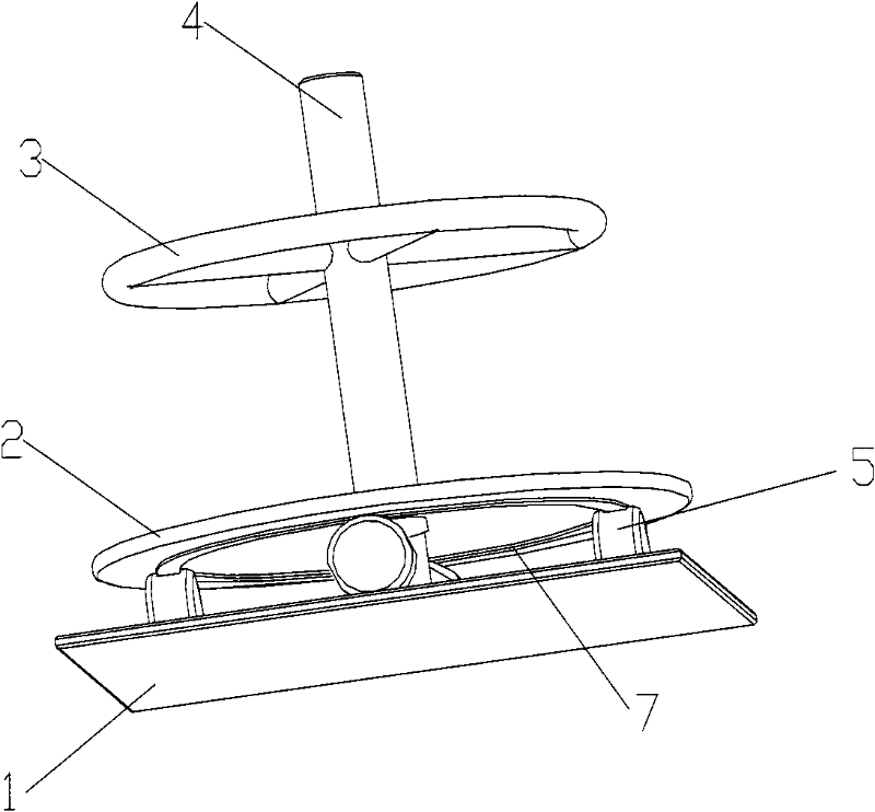
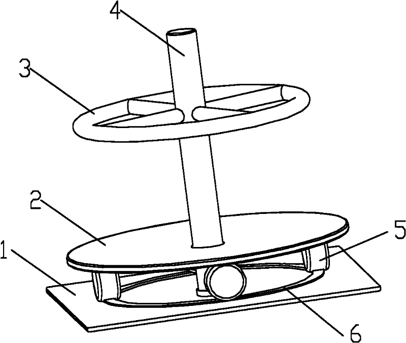
[0013] as attached figure 1 , 2 Shown is a large steel wire pay-off device of the present invention, comprising a support plate 1, a vertical shaft 4, and a roller 5, the vertical shaft 4 is vertically arranged on the support plate 1; the near upper end of the vertical shaft 4 is provided with a retaining ring 3; the near lower end of the vertical shaft 4 is provided with a support plate 2; a bearing is provided between the support plate 2 and the vertical shaft 4; the roller 5 is arranged between the support plate 1 and the support plate 2; The support plate 1 is provided with a circular first slide rail 6; the lower surface of the support plate 2 is provided with a circular second slide rail 7; the roller 5 is arranged on the first slide rail 6 and the second slide rail 7 Between; the first slide rail 6 and the second slide rail 7 are protruding outward; the roller 5 is provided with a groove; the groove is sleeved on the protrusion.

[0014] Due to the application of the ...


PUM


Abstract

The invention discloses a large-scale steel wire release device, which comprises a bearing plate, a vertical shaft and a roller, wherein the vertical shaft is arranged on the support plate vertically; a check ring is arranged near upper end part of the vertical shaft; a support plate is arranged on the near lower end part of the vertical shaft; a bearing is arranged between the support plate and the vertical shat; and the roller is between the bearing plate and the support plate. In the large-scale steel wire winding device, the support plate is arranged on the near lower end part of the vertical shaft; the bearing is arranged between the support plate and the vertical shat; the roller is arranged between the bearing plate and the support plate; a first circular sliding rail is arranged on the bearing plate; the lower surface of the support plate is provided with a second circular sliding rail; the first sliding rail and the second sliding rail are both bulged outwards; a groove is formed on the roller; the roller is arranged between the first sliding rail and the second sliding rail; and the groove is sleeved on bulges. By the structure, more steel wires can be supported, and the mobility of the support plate is better.

Description

technical field [0001] The invention relates to a steel wire pay-off device, in particular to a large-scale steel wire pay-off device, which belongs to the technical field of steel wire winding. Background technique [0002] In the manufacturing process of steel wire drawing, various types of steel wires are used to process the raw materials of steel wires in the process of releasing wires, and there are certain specifications, such as steel wire diameter, weight, etc.; when it comes to steel wire product processing enterprises, according to the needs , the steel wire bought from the steel mill is often drawn, and the diameter of the steel wire becomes smaller; if the steel wire raw material bought from the steel mill is relatively heavy, a wire pay-off device is needed. A common wire pay-off device includes a support, Vertical shaft and a hollow shaft sleeve, the vertical shaft is vertically arranged on the support; both ends of the hollow shaft sleeve are provided with baf...

Claims


Application Information

Patent Timeline
IPC IPC(8): B65H49/18B65H49/20
Inventor 黄伟良颜慧珍
Owner JIANGSU SHENWANG GROUP
Learn More