Eureka AIR delivers breakthrough ideas for toughest innovation challenges, trusted by R&D personnel around the world.

Rear wheel suspension with coil springs with an inclined reaction force axis

A line of action and suspension technology, applied in the direction of elastic suspension, suspension, vehicle spring, etc., can solve the problems of easy to hear, etc., and achieve the effect of reducing weight, increasing movement, and reducing fuel consumption

Inactive Publication Date: 2011-10-12
FORD GLOBAL TECH LLC
View PDF10 Cites 4 Cited by
  • Summary
  • Abstract
  • Description
  • Claims
  • Application Information

AI Technical Summary

Problems solved by technology

In addition to the additional components required to install a Watts three-link suspension, an additional sound channel is created where occupants in the vehicle may be prone to some annoying noises

Method used


Image

  • Rear wheel suspension with coil springs with an inclined reaction force axis
  • Rear wheel suspension with coil springs with an inclined reaction force axis
  • Rear wheel suspension with coil springs with an inclined reaction force axis

Examples


Embodiment Construction

[0027] In the different figures, the same parts always have the same references, and for this reason the above-mentioned parts are generally only described once.

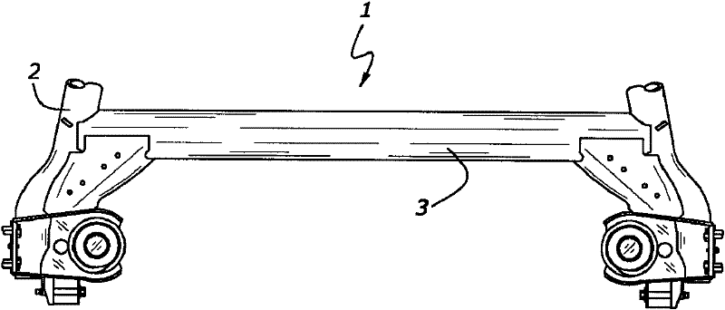
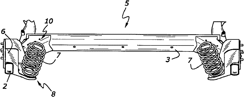
[0028] figure 2 Indicates as according to the known technology figure 1 The shown rear wheel suspension 5 is embodied by way of example as a semi-independent axle 5 . The semi-independent axle 5 has a longitudinal pivot arm 2 assigned to each hub carrier 6 . The longitudinal pivot arms 2 are connected to one another via a section 3 . The longitudinal pivoting arms 2 and the profiles 3 or structural elements of the rear wheel suspension 5 can have many different designs, but no further details will be given here.

[0029] Bearing bushings are likewise arranged on the longitudinal pivot arm 2 , but are not shown.

[0030] Each longitudinal oscillating arm 2 is assigned a spring 7, which in a preferred embodiment is a helical spring 7, which bears on the respective longitudinal oscillating arm 2 at one end, i.e. t...


PUM


Abstract

The invention relates to a rear wheel suspension 1 with coil springs with an inclined reaction force axis, which has a spring 7, preferably embodied as a coil spring 7 that has a geometric spring center line and a line 9 of action of force, the coil spring 7 being supported in an upper and a lower spring mount. In order to reduce the forces imposed on structural elements of the rear wheel suspensio 1n, the proposal is that the spring 7 be embodied and arranged in such a way that the line 9 of action of force thereof has an amount of tilt during an inward deflection which is different from an amount of tilt during an outward deflection.

Description

technical field [0001] The invention relates to a rear wheel suspension having a spring, which in a preferred embodiment is a helical spring having a geometrical spring center line and a line of action of force, which is supported in an upper spring seat and a lower spring seat , when turning, the wheel or associated coil spring on the outside of the bend deflects inward, and the wheel or associated coil spring on the inside of the bend deflects outward. Background technique [0002] Rear wheel suspensions of this type are known, for example, as semi-independent axles. [0003] German patent document DE 10 2004 058 698 B3 discloses a wheel suspension or movable chassis comprising a body, wheels movably connected to the body by means of a linkage arrangement, which has a hub bracket and at least one helical compression spring , One end of the helical compression spring is supported on the vehicle body, and the other end is supported on the hub bracket or connecting rod arran...

Claims


Application Information

Patent Timeline
Patent Type & Authority Applications(China)
IPC IPC(8): B60G17/02B60G11/14
CPCB60G3/00B60G9/00B60G11/00B60G11/14B60G21/051B60G2200/20B60G2200/462B60G2202/12B60G2202/136B60G2204/1246B60G2206/426
Inventor 安德列斯·卡利茨西奥·屈佩尔斯简斯·格洛勒
Owner FORD GLOBAL TECH LLC
Why Eureka
Eureka Blog
Learn More