
Antifoaming device used for biological fermentation

A defoaming device and bio-fermentation technology, applied in biochemical cleaning devices, enzymology/microbiology devices, bioreactor/fermentation tank combinations, etc., can solve cleaning and sterilization dead ends, bacterial contamination, and loss of fermentation broth and other problems, to achieve the effect of simple structure, easy cleaning, and reduced dosage

Active Publication Date: 2011-10-05
常州三高生物技术工程设备有限公司
View PDF4 Cites 3 Cited by
  • Summary
  • Abstract
  • Description
  • Claims
  • Application Information

AI Technical Summary

Problems solved by technology

[0002] The aeration and stirring fermentation process is often accompanied by the generation of a large amount of foam, which not only easily causes the loss of "escaping liquid" of the fermentation liquid, reduces the loading amount of the fermenter, but also increases the risk of bacterial contamination
The addition of too many chemical defoamers not only increases the cost of fermentation production, but also reduces the oxygen transfer rate in the fermentation process, reduces the fermentation yield, and may affect product extraction efficiency and product quality
[0003] The various mechanical defoaming devices currently designed can reduce the amount of chemical defoaming agents in a certain period of time and to a certain extent, but for the stubborn foam in the middle and late stages of the fermentation process, simple devices are often unable to do what they want, while complex devices are easy to produce Clean and sterilize the dead corners, leading to the contamination of bacteria

Method used


Image

  • Antifoaming device used for biological fermentation
  • Antifoaming device used for biological fermentation
  • Antifoaming device used for biological fermentation

Examples


Embodiment Construction

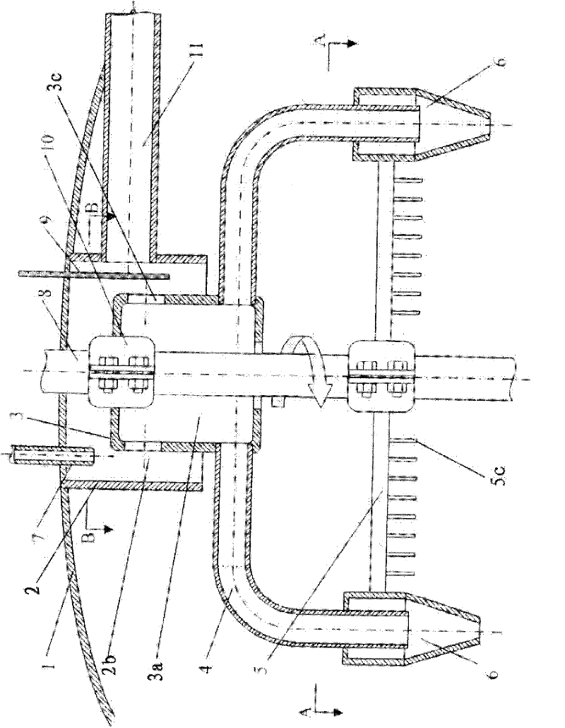
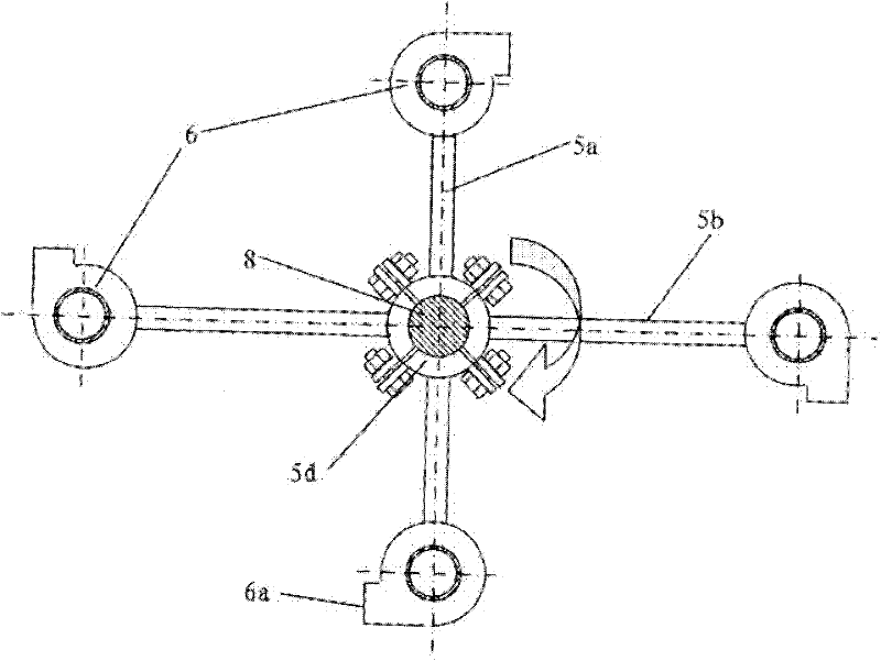
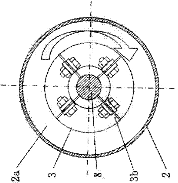
[0015] refer to Figure 1 to Figure 3 , the bio-fermentation defoaming device of the present invention mainly consists of a fermenter 1, a stirring shaft 8, a static cylinder 2, a rotating device 3, a gas-liquid separation device, and a foam breaking device. The following is for each part and between each part The structure is described in detail (the fermenter and the stirring shaft are existing components, so they will not be described in detail):

[0016] A static cylinder 2 with a static cavity 2a is fixed on the inner top wall of the fermenter 1 by welding, and the lower end of the stirring shaft 8 passes through the static cavity 2a of the static cylinder 2 . A hole is arranged on the side wall of the static cylinder 2, and one end of the exhaust pipe 11 is inserted into the hole to communicate with the static cavity 2a of the static cylinder, and the other end of the exhaust pipe 11 passes through the side wall of the fermenter. The static cylinder is stationary during...


PUM


Abstract

The present invention discloses an antifoaming device used for biological fermentation. The device comprises a fermentation tank and a stirring shaft, wherein a stationary cylinder with a stationary cavity is fixed on the inner top wall surface of the fermentation tank, an exhaust pipe communicated with the stationary cavity is formed on the sidewall surface of the stationary cylinder, the lower part of the stirring shaft penetrates from the stationary cavity of the stationary cylinder, a rotating device with a rotating cavity is peripherally fixed on the stirring shaft, the upper part of therotating device is located in the stationary cavity of the stationary cylinder, the upper sidewall surface of the rotating device is equipped with at least 2 through holes, the lower part of the rotating device extends out of the stationary cavity, and the lower sidewall surface of the rotating device is equipped with a gas-liquid separation device. The antifoaming device provided by the invention can be used for antifoaming in the ventilation and stirring fermentation processes widely applied in the fermentation production of medicaments, foods and chemical products, thus reducing the escapeloss of fermentation liquid and saving antifoaming agent.

Description

technical field [0001] The invention relates to the field of biological engineering equipment, in particular to a biological fermentation defoaming device. Background technique [0002] The aeration and stirring fermentation process is often accompanied by the generation of a large amount of foam, which not only easily causes the loss of "escaping liquid" of the fermentation broth, reduces the loading amount of the fermenter, but also increases the risk of bacterial contamination. The addition of too many chemical defoamers not only increases the cost of fermentation production, but also reduces the oxygen transfer rate during the fermentation process, reduces the fermentation yield, and may affect the product extraction efficiency and product quality. [0003] The various mechanical defoaming devices currently designed can reduce the amount of chemical defoaming agents in a certain period of time and to a certain extent, but for the stubborn foam in the middle and late stag...

Claims


Application Information

Patent Timeline
IPC IPC(8): C12M1/21C12M1/02
CPCC12M41/02C12M27/02
Inventor 李德高徐亲民
Owner 常州三高生物技术工程设备有限公司
Learn More